Sunday, May 23, 2021

INSTRUMENTS CABLES QUESTIONS & ANSWER


Instrumentation Cables Questions & Answers


Instrumentation Cables Questions & Answers

Instrumentation Cables Questions Answers

Cables Questions and Answers

Explain different Control and Instrumentation Cables ?

Instrumentation cables are multiple conductor cables that convey low energy electrical signals used for monitoring or controlling electrical power systems and their associated processes.

The functions of measurement and control are vital in manufacturing and processing applications. These functions are greatly dependent on their electronic circuitry.

Typical applications include industrial equipment control, broadcasting, assemble equipment, or mass transit systems.

Different types of Instrumentation Cables are as follows :

ARCNET cables are used in high-speed, token-based, ARCNET networks that provide local area network (LAN) communications between industrial computers.

AS-I cables are used to interface binary actuators, sensors, and other AS-i devices. These two-core cables supply power and transfer data.

CANbus cables are used in high-speed, serial data networks that are designed for harsh electrical environments. They are used widely in the automotive industry.

CANopen cables are used with an industrial communications fieldbus protocol that is based on CANbus.

DeviceNet cables also use the controller area network (CAN) protocol, but typically connect devices such as limit switches, photoelectric cells, valve manifolds, motor starters, drives, and operator displays to programmable logic controllers (PLCs) and personal computers.

Fieldbus cables are used to connect industrial devices such as actuators, sensors, transducers, and controllers. In the hierarchy of plant networks, the fieldbus environment is the base level group.

Foundation Fieldbus cables are used in an all-digital, serial, two-way communications system that serves as a LAN for plant instrumentation and factory control devices.

HART cables allow communications without interrupting a 4-20mA signal. They allow a host application (master) to get two or more digital updates per second from a field device.

PROFIBUS cables use a vendor-independent fieldbus standard that is suitable for both process automation and manufacturing applications.

P-Net cables conform to a European standard (EN 50 170 Vol. 1) that is now part of the International Fieldbus Standard (IEC 61558 Type 4).

What is Cable Shielding ?

Control and instrumentation cables may feature a type of electromagnetic shielding material, which is wrapped around the cable underneath the outer jacket.

Cable Shielding

Shielding serves to prevent electrical noise from affecting the transmitted signal, and to reduce electromagnetic radiation emission from the cable itself.

Shielding is typically comprised of metal braiding, metal tape or foil braiding. A shielded cable assembly may also feature a special grounding wire known as a drain wire.

How do we determine the rating of a cable?

The continuous current rating of a cable is determined by the ability of the cable to dissipate the heat generated by the current passing through its conductor.

It depends on a number of parameters, but the most important are the:

  • Conductors’ DC resistance;
  • Thermal resistance of the insulating sheathing materials; and
  • Ambient conditions of the environment where the cable is installed (for example the surrounding air temperature).

Differences between solid and stranded conductors?

Solid conductors are constructed of one, single piece of metal.  It is tougher than a stranded conductor, but rigid and less flexible than a stranded conductor.

Solid conductors are more likely to break if subjected to frequent flexing than stranded conductors.

Stranded conductors are made of multiple small strands, which group together to make up a single conductor.  It is more flexible than a solid conductor, but less durable.

Stranded Constructions:

Bunch Stranding , Concentric Stranding, Unilay Stranding, Rope Lay Stranding

  • Bunch stranding is a collection of strands twisted together in the same direction without regard to the geometric arrangement.
  • Concentric stranding consists of a central wire or core surrounded by one or more layers of helically laid wires. Each layer after the first has six more wires than the preceding layer. Except in compact stranding, each layer is usually applied in a direction opposite to that of the layer under it.
  • Unilay stranding is the same as true concentric; except that the lay length is the same in each layer. Normal direction of lay is left-hand.
  • Rope lay stranding is a concentrically stranded conductor, each of whose component strands are they themselves stranded.  A rope stranded conductor is described by giving the number of groups laid together to form the rope along with the number of wires in each group.

Differences between Cable Jackets & Insulations ?

A jacket is an outer sheath that protects the wire or cable core from mechanical, moisture and chemical issues.

Jackets help with flame resistance, protect against sunlight and facilitate installation. Jackets come in a variety of types and styles and are mainly plastic or rubber based.

Differences between Cable Jackets & Insulations

Insulation is a coating that is extruded or taped onto bare wire to separate conductors from each other electrically and physically. There are a variety of insulation types for different applications.

Types of Jackets & Insulations ?

Thermoplastic

Thermoplastics are the primary insulation and jacket used in wire and cable. A Thermoplastic is a material that softens when heated and becomes firm when cooled. Thermoplastics come in a variety of different types each with its own set of characteristics.

Types: PVC, Fluoropolymers, Polyolefins, TPE

Thermoset

Thermoset plastics are a group of compounds that are hardened or set by the application called cross-linking. Cross-linking is accomplished by a chemical process, vulcanization (heat & pressure) or irradiation.

Types: CPE, XLPE, EPR, Silicone Rubber

Fiber

Fiber jackets are commonly used in high temperature applications due to their excellent heat resistance. Fiber jackets are also flame resistant and can be used as overbraids for silcone rubber insulation.

What is the purpose of the screens in instrumentation cables?

The presence of large machines, welders and other processes in industrial environments create a lot of electrical interference (noise).

This noise has the potential to distort the clarity of signals that are transmitted between equipment, which may lead to false readings.

For example, a system monitoring the temperature of a boiler may not report the correct temperature. A metallic screen will shield the cores of a cable from interference, thus improving the clarity of a signal.

If a cable has a fire rating, does this mean that it won’t burn?

Fire rated cables are designed to continue functioning during the course of a fire for a specific period of time which allows for safe evacuation of a building by maintaining smoke handling systems, emergency lighting etc. The cable will burn however in a manner that ensures circuit integrity during the fire.

Can a cable with a fire rating operate continuously in hot environments, for example, very close to a furnace?

No, a cable with a fire rating does not necessarily mean that is it suitable for use in a hot environment.

It is necessary to design cables using special materials such as silicone or glass fibre to withstand relatively high temperatures (in excess of 110°C on a continuous basis.)

What standards / guidelines are available for cable tray systems?

1. The National Electrical Code publishes the standards for all types of electrical applications. Articles 318, 250, and 800 cover various aspects of cable tray systems.

2. NEMA, (National Electrical Manufacturers Association), is an association comprised of the major cable tray manufacturers in the industry. This committee has published three documents to date: NEMA VE1, FG1 and VE2.

NEMA VE1 covers general cable tray definitions, manufacturing standards, performance standards, test standards, and application information.

NEMA FG1 addresses the standards for fiberglass cable tray systems.

NEMA VE2 is a cable tray installation guideline which covers receiving and unloading material, storage of material, and general installation practices.

What is the difference between the Power & Control Cables?

Power Cables – No. of Cores 2,3, 3 1/2 & 4 Core

Control Cables – Upto 63 Cores or above Standards Applicable for both – IS-694 & IS-1554 .

What is the difference between Unsheathed & Sheathed Single Core Cable as per IS-694?

Unsheathed – Only Core Insulation will be done and there will be no Sheathing.

Sheathed – Sheathing will be done on Core Insulation.

What is the difference between Control & Instrumentation Cable?

Control Cables – They are generally Core Constructed.

Instrumentation Cables – They are generally Pair Constructed with Shielding.

What is the difference between Thermocouple & Instrumentation Cable?

Conductor Material is different for both.

What is the difference between Armoured & Unarmoured Cable?

a. Armour.

b. Inner Sheath will be provided for Armoured Cable before Armouring.

What is a Co-Axial Cable?

This type of cable is used for Very High Frequency (V.H.F.) Applications.

What is the Voltage Grade?

Low Voltage Grade — upto and including 1.1 KV

High Voltage Grade — above 1.1 KV

Number of Strands for Cables ?

a. Solid Conductor – One

b. Multistrand – either 3 or 7

c. Flexible – No of Strands above 7 – Dia of Strands upto 0.3 mm .

Dia of Strands for 1.5 Sq.mm can be:

a. Incase of 7 Strands – 7/0.52

b. Incase of 0.3 mm dia each – 21 Strands

c. Incase of 0.2 mm dia each – 48 Strands.

What is the Core / Pair Identification incase of LDPE Insulated Cable?

By Colour or By Number printed Al-Mylar Tape / Polyster Tape.

What is the Purpose of Screening?

To reduce the interference by nearby sources.

What are the different types of Screenings?

a. Al-Mylar / Cu-Mylar Tape

b. ATC or ABC Braiding.

What will be the Normal Insulation Thickness for Telephone Cables?

a. Core Insulation – 0.2, 0.3 mm

b. Sheath – 0.5 to 1.2 mm.

What is the difference between RTD / Instrumentation Cable?

RTD Cables will be Triad Constructed.

Instrumentation Cables are Pair constructed.

What are the normal sizes of Control Cables?

1.5 & 2.5 Sq.mm

What will be the normal Conductor sizes for instrumentation / RTD Cables?

0.5, 0.75, 1.0, 1.5 & 2.5 Sq.mm

Thermocouple Cable Conductor normal sizes ?

a. Single pair – 16 AWG (1.295 mm dia)

b. Multi pair – 20 AWG (0.813 mm dia)

What is the Temperature Tolerance (+/- deg. C) allowable for Thermocouple cables?

a. IS 8784 +/- 3 Deg. C

b. ANSI MC 96.1 +/- 2.2 Deg. C

Colour code as per IS 1554 for Core constructed Cables ?

a. Upto 5 Cores by different colours i.e for 2 Cores Red & Black, for 3 Cores Red, Yellow & Blue, for 4 cores Red, Yellow, Blue & Black, for 5 Cores Red, Yellow, Blue, Black & Grey.

b. Above 5 Cores : One Core Yellow and One Core Blue remaining Grey in each layer (or) any single colour with numbers printed.

For above 5 Cores Grey with number printing is our normal practice.

What are the 3 types of Braided (Metal Braiding) Cables manufactured?

a. Annealed Tinned Copper Braided Cables

b. Annealed Bare Copper Braided Cables

c. Nickle Plated Copper Braided cables

d. G.I. Braided Cables.

What is the Temperature with standability of PTFE & Fibre Glass?

PTFE – 250 Deg.C, FG Cables 400 Deg.C


BASIC OF TRIPS, INTERLOCKS, PERMISSIVES & SEQUENCES


Basics of Trips, Interlocks, Permissives & Sequences


This post provides information about basics of Trip, Interlock, Permissive and Sequences which are regularly used in instrumentation control systems like ESD, DCS, PLC etc.

Trip:

The term Trip refers to an action that is initiated by the control system and which forces a device or devices to a pre-determined state.
Example of Trip Signals: Close Valve, Open Valve, Stop motor, etc.
The Safety Instrument System (SIS) or a Hardwired systems normally initiate trips, however the PLCs or DCS may also initiate trips provided the necessary independence and SIL ratings are met.
Once a device or devices have been forced to a pre-determined state by the action of a Trip they will remain in that state until the Trip is manually reset by a conscious operator action.
For example:
  • High level in a vessel initiates a trip system which stops the pump feeding that vessel, the pump will remain stopped even if the level in the vessel falls to a safe level.
  • The Trip must be ‘reset’ by the operator before the pump can be re-started.
  • The Trip can only be ‘reset’ if the level in the tank has fallen to a safe level.
  • Resetting the Trip will not cause the pump to automatically re-start, however it may be re-started by an operator action or a control system command e.g. part of a sequence.
The resetting of Trips is a controlled procedure which will only be possible if the operator is logged in and has the necessary access rights.
Under normal circumstances it shall not be possible to ‘override’ or `defeat’ Trips.

Interlock:

An Interlock is in essence a ‘self resetting’ Trip. Interlocks are not deemed safety related and can be used for on/off control.
Interlocks are normally initiated by the DCS or PLCs, however if an Interlock is deemed to be safety related it may, depending upon SIL rating, be implemented in the SIS or a Hardwired system.
An interlock will force a device or devices to a pre-determined state e.g. Close valve, stop motor, etc.
Once a device or devices have been forced to a pre-determined state by the action of an Interlock they will remain in that state until the initiating cause returns to a ‘healthy’ condition, the Interlock will then be automatically removed.
Under normal circumstances it shall be possible to ‘override’ Interlocks for operational reasons or ‘defeat’ them for maintenance or other reasons.

Permissive:

A Permissive is a patricular type of Interlock used to prevent actions taking place until pre-defined criteria have been satisfied, for example prevents a pump starting until the suction valve is open.
Permissives are normally initiated by the DCS or PLCs, however if a Permissive is deemed to be safety related it may, depending upon SIL rating, be implemented in the SIS or a Hardwired system.
Once a Permissive has been satisfied and the resulting action implemented it becomes inactive, for example once the suction valve has been opened and the pump started the Permissive takes no further action, even if the suction valve is closed while the pump is running.
Under normal circumstances it shall be possible to ‘override’ Permissives for operational reasons or ‘defeat’ them for maintenance or other reasons.

Sequence:

A Sequence is defined as a pre arranged action or number of actions which are carried out by the control system. Sequences may be initiated by an event or operator actions.
Sequences may be ‘single pass’ or ‘cyclic’.
The following is an example of a ‘single pass’ sequence:
An agitated vessel reaches a pre-determined level. The operator initiates a sequence that carries out the following actions:
  • Stop the feed pump
  • Close the filling valve
  • Stop the agitator.
  • Wait 30 seconds.
  • Open the discharge valve.
The following is an example of a ‘cyclic’ sequence:
  • Low level in a vessel opens the filling valve.
  • The valve remains open until high level is detected.
  • On high level the valve closes.
  • The valve remains closed until low level is detected.
  • On low level the valve opens and the sequence it repeated.

Combined Functions:

It is common for Trip, Interlock, Permissive and Sequences to fulfill combined functions, for example the following pump protection system illustrates how the same system can perform various functions.
Permissive
Prevent pump starting until suction valve is open.
Interlock
Pump running – suction valve closed-pump stops.
Sequence
High level in vessel-Pump stops
Low level in vessel-Pump starts.
Pump running – suction valve closed – pump stops,
Suction valve re-opened – pump remains stopped.
Operator resets trip.
Pump available for re-start.

WHAT ARE ANALOG & DIGITAL SIGNALs? DIFFERENCES, EXAMPLES


What are Analog and Digital Signals? Differences, Examples


What is a Signal?

Gestures, actions, sounds, expressions tell us some information, and these are the ways of communicating one to other. Similarly signal is a way of communicating by sending information from one system to other system. In other words signal is a function that represents information or data.

Signal is an electromagnetic wave that carries information through physical medium. Here the data is converted into electromagnetic signal either as analog or digital and sent from sender to receiver.

Voltage and current are few time varying quantities that are used to represent data, by varying these quantities with respect to time data can be transmitted. Similarly signal is also represented as the function of the frequency domain rather than time domain.

For communicating between two systems, a message signal is passed through encoder and modulator to transmit through a medium while it is passed through decoder and demodulator to receive the message signal at the other end.

Signals are divided into two categories based on their nature. 

Signals which are

  1. Signal which are Continuous as time varying in nature are analog signals                               
  2. Signal which are discrete are called digital signals.
What are Analog and Digital Signals

Analog Signals

Analog signal is a form of electrical energy (voltage, current or electromagnetic power) for which there is a linear relationship between electrical quantity and the value that the signal represents.

The signal whose amplitude takes any value in a continuous range is called analog signal.

Analog Signals are continuous in nature which vary with respect to time. They can be periodic or non-periodic.

Voltage, current, frequency, pressure, sound, light, temperature are the physical variables that are measured with respect to their changes with respect to time to obtain information.

When voltage versus time graph is plotted we see curve with continuous values like sine waves.

These signals are more subjected to noise as they travel through the medium, these noises result in information loss in the signal. 

Analog to digital converter converts analog signal to digital signal by a process called sampling and quantization. Sound waves are converted to sequence of samples by the process Sampling

Examples of analog signals:

Conventional (old) transmitters, transducers convey data in analog mode.

The signals include audio signals transmitted through wires, video signals broadcasted using older technology, radio signals, and analog watches.

Digital Signals

The signal, whose amplitude takes only limited values is called Digital signal.

Digital signal are discrete, they contain only distinct values. 

Digital signals carry binary data i.e. 0 or 1 in form of bits, it can only contain one value at a period of time. Digital signals are represented as square waves or clock signals.

The minimum value is 0 volts whereas maximum value is 5 volts.

Digital signals are less subjected to noise compared to analog signal.

Transmission of digital data in analog channel is done by process called Modulation.

Amplitude modulation is a process in which digital data is converted to analog signals using single frequency carrier signal. Similarly FREQUENCY shift keying uses a constant amplitude carrier signal and two frequencies to differentiate between 1 and 0.

Nowadays usage of digital signals for transmitting information has increased rapidly in every field of usage as the applications and properties of digital signals are more productive compared to analog signals.  

Examples of digital signals:

  • Smart transmitters using various protocols transmit data through analog and digital signals.
  • Digital watches.
  • Digital video signals.
  • CD’s.
  • DVD’s.
  • Computer.

Difference between Analog and Digital Signals

Analog SignalsDigital Signals
Analog signal is continuous and time varying.Digital signal have two or more states and in binary form.
Troubleshooting of analog signals are difficult.Troubleshooting of digital signals are easy.
An analog signal is usually in the form of sine wave.An digital signal is usually in the form of square wave.
Easily affected by the noise.These are stable and less prone to noise.
Analog signals use continous values to represent the data.Digital signals use discrete values to represent the data.
Accuracy of the analog signals may be affected by noise.Accuracy of the digital signals are immune from the noise.
Analog signals may be affected during data transmission.Digital signals are not affacted during data transmission.
Analog signals use more power.Digital signals use less power.
Examples: Temperature, Pressure, Flow measurements, etc.Examples: Valve Feedback, Motor Start, Trip, etc.
Components like resistors, Capacitors, Inductors, Diodes are used in analog circuits.Components like transistors, logic gates, and micro-controllers are used in Digital circuits.


BASIC OF 4-20mA CURRENT LOOP


Basics of 4-20mA Current Loop


The 4-20 mA current loop is a very robust sensor signaling standard.  Current loops are ideal for data transmission because of their inherent insensitivity to electrical noise.

In a 4-20 mA current loop, all the signaling current flows through all components; the same current flows even if the wire terminations are less than perfect.

All the components in the loop drop voltage due to the signaling current flowing through them. The signaling current is not affected by these voltage drops as long as the power supply voltage is greater than the sum of the voltage drops around the loop at the maximum signaling current of 20 mA.

Basics of 4-20mA Current Loop

4-20mA Current Loop

Figure 1 shows a schematic of the simplest 4-20 mA current loop.

There are mainly four components:
  1. A DC power supply;
  2. A 2-wire transmitter;
  3. A receiver resistor that converts the current signal to a voltage;
  4. The wire that interconnects it

The two “Rwire” symbols represent the resistance of the wires running out to the sensors and back to the power supply (Power supply means IO cards or barriers).

Basics of Current Loop

In Figure 1, current supplied from the power supply flows through the wire to the transmitter and the transmitter regulates the current flow within the loop.  The current allowed by the transmitter is called the loop current and it is proportional to the parameter that is being measured.

The loop current flows back to the controller through the wire, and then flows through the Rreceiver resistor to ground and returns to the power supply(IO card or barrier).

The current flowing through Rreceiver produces a voltage that is easily measured by an analog input of a controller.  For a 250Ω resistor, the voltage will be 1 VDC at 4 mA and 5 VDC at 20 mA.

4-20mA Current Loop Components:

1. The Power Supply

Power supplies for 2-wire transmitters must always be DC because the change in current flow represents the parameter that is being measured. If AC power were used, the current in the loop would be changing all the time.

Therefore, the change in current flow from the transmitter would be impossible to distinguish from change in current flow caused by the AC power supply.

For 4-20 mA loops with 2-wire transmitters, common power supply voltages are 36 VDC, 24 VDC, 15 VDC and 12 VDC.

Current loops using 3-wire transmitters can have either AC or DC power supplies.  The most common AC power supply is the 24 VAC control transformer or 230A Ac.

Be sure to check any transmitter’s installation literature for the proper voltage requirements.

For a 2 wire transmitter the power supply is a IO card in System Cabinet or a Barrier in Marshalling Cabinet.

2. The Transmitter

The transmitter is the heart of the 4-20 mA signaling system.This is the device used to transmit data from a sensor over the two-wire current loop. There can be only one Transmitter output in any current loop. It acts like a variable resistor with respect to its input signal and is the key to the 4-20mA signal transmission system.

The transmitter converts the real world signal, such as flow, speed, position, level, temperature, humidity, pressure, etc., into the control signal necessary to regulate the flow of current in the current loop. The level of loop current is adjusted by the transmitter to be proportional to the actual sensor input signal.

An important distinction is that the transmitted signal is not the current in the loop, but rather the sensor signal it represents. The transmitter typically uses 4mA output to represent the calibrated zero input or 0%, and 20mA output to represent a calibrated full-scale input signal or 100%

Generally the power to transmitters as a range, 12 to 36 VDC The lower voltage is the minimum voltage necessary to guarantee proper transmitter operation.  The higher voltage is the maximum voltage the transmitter can withstand and operate to its stated specifications.

A common misconception about Transmitters is that they source the loop current, but the transmitter is not the source of the current. Rather, it is a series connected current-sinking circuit that will attempt to draw current from a power supply wired to its output terminals.

The current in the loop is the medium via which the sensor signal is transmitted. The current flowing through the transmitter is proportional to the input signal being measured. When calibrated properly, this current will vary from 4 to 20mA over the range of its sensor input signal. The transmitter will also make allowances to support under-range and over-range output current levels.

3. The Receiver Resistor

It is much easier to measure a voltage than it is to measure a current.  Therefore, many current loop circuits (such as the circuit in Figure 1) use a Receiver Resistor (Rreceiver) to convert the current into a voltage.

In Figure 1, Rreceiver is a 250Ω precision resistor. The current flowing through it produces a voltage that is easily measured by an analog input of a controller.

For the 250Ω resistor, the voltage will be 1 VDC at 4 mA of loop current and 5 VDC at 20 mA of loop current. The most common Receiver Resistor in a 4-20 mA loop is 250Ω; however, depending upon application, resistances of 100Ω to 750Ω may be used.

4. The Wire

The impact of the wire resistance in the current loop is often ignored, as it usually contributes negligible voltage drop over short distances and small installations.

However, over long transmission distances, this drop can be significant and must be accounted for, as some current loop installations will use wire distributed over hundreds and even thousands of feet.

To illustrate the impact of wire resistance, the following table lists the resistance of common copper wire gauges.

Sending current through a wire produces a voltage drop proportional to the length and thickness (gauge) of the wire. Generally 1.5 Sqmm thickness cable will be preferred, However depending on the application or plant design 0.5 Sqmm, 2.5 Sqmm, 3Sqmm, 6Sqmm etc… will also be used.Copper Wire Resistance Gauge vs ohms

All wire has resistance, usually expressed in Ohms per 1,000 feet.

The voltage drop can be calculated using Ohm’s law:

E = I x R

E = the voltage across the resistor in volts;
I =the current flowing through the conductor in amperes;
R = the conductor’s resistance in Ohms.

Wire resistances for common wire gauges are shown in Table 1 above.

As an example of the potential impact wire resistance can have on an installation, let’s assume that we have wired our loop elements together using 3000 feet of 24 AWG. Note that 3000 feet is the total round-trip length of wire. Thus, we can calculate a wire resistance of 3000ft*26.2Ω/1000ft =78.6Ω. This will result in a voltage drop of 0.022A* 78.6Ω =1.73V at a maximum loop current of 22mA.

If you find yourself having to do these kinds of calculations often, but you do not have an AWG Copper Wire Chart handy, you can approximate the wire resistance of a given gauge by committing three points to memory:

40 AWG copper wire is approximately 1Ω per foot (refer to Table 1 and see 40AWG is 1070Ω per 1000 feet, or 1.07Ω per foot).

Every 10 wire gauges lower divides resistance by 10 (refer to Table 1 and note that 30AWG is 105.2Ω per 1000 feet, or 0.1Ω per foot).

Every 3 wire gauges lower halves the resistance.

For example, to approximate the resistance of 24AWG copper wire, without having to refer to a table, you can do the math in your head as follows:

Remembering that 40AWG is 1Ω/foot. Then 10AWG lower is 30AWG and one-tenth of this, or 0.1Ω/foot. Then 3 AWG lower is 27AWG at one half of this, or 0.05Ω/foot. Then 3 AWG lower at 24AWG is one half of that, or 0.025Ω/foot.

Now check this against Table 1 and note that 24AWG wire is actually 26.17Ω per 1000 feet, or 0.02617Ω per foot. Our approximation is less than 5% from the value in Table 1. You will note slight differences in wire resistance values from manufacturer to manufacturer.

Insensitivity to Electrical Noise

The greatest advantage of using a current loop for data transmission is a current loop’s inherent insensitivity to electrical noise.  Every transmitter has some output resistance associated with it.

Ideally, the current transmitter’s output resistance would be infinite.  However, real world transmitters have very large but not infinite output resistances.This output resistance can be represented as a resistor in a circuit schematic.

The circuit schematic at right (Figure 2) shows the component resistances of a 4-20 mA current loop with a noise source added to the loop.

Because of the high output resistance of the transmitter(3.64MegΩ), the vast majority of the noise voltage is dropped across the transmitter, and only a tiny fraction is dropped across the Rreceiver. Since the controller sees only the voltage across the Rreceiver, the noise voltage has almost no effect upon the controller.

Current Loop Noise Reduction Example:

If the noise source in Figure 2 has an amplitude of 20 Volts, then the noise voltage seen across the Rreceiver is onlyCurrent Loop Noise
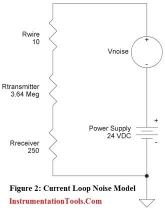
0.0014 volts. This is because the noise voltage measured across any resistor is equal to the Ohms of that resistor divided by the total Ohms in the circuit multiplied by the noise voltage.

Voltage Noise at Rreceiver =

Vnoise x Rreceiver/(Rwire+Rtransmitter+Rreceiver)

Vnoise = 20 x 250/3,640,260 = 0.0014 volts

The voltage across Rreceiver at 20 mA of loop current is five volts.  Adding 0.0014 volts of noise is only 0.028% of five volts, which is an insignificant error.

If the power supply of Figure 1 is varied such that the voltage dropped across the transmitter varies from 7 to 24 VDC, the output current only changes by 0.000005 amps, or 5 micro-amps. This equals only 0.00125 volts across the 250Ω Rreceiver resistor, which is an insignificant fluctation.

What makes 4-20mA signal transmission so attractive?

While we’ve reviewed some of the fundamentals of 4-20mA two-wire current loops and the basic loop elements, and we have an idea of how they work together, let’s consider some of the advantages of 4-20mA signal transmission.

Probably the greatest advantage of using a current loop for signal transmission is the current loop’s low sensitivity to electrical noise. This is very important for long distance transmission in harsh industrial environments. As a generally low impedance system, it is much less sensitive to induced noise, than perhaps the high impedance input of a voltage amplifier.

The currents injected by typical noise sources are generally no more than a few hundred micro-amps, usually insignificant to the 16mA span. The use of a “Live Zero” also improves the signal to noise ratio at low levels, allowing us to accurately discern low signal levels without added noise or interference.

Another advantage to the 4-20mA current loop is that it is essentially lossless with respect to the transmission media (wire) and the interconnections (connectors). That is, the accuracy of the signal is not affected by the voltage drop in the interconnecting wiring. This allows the signal transmission to occur over long distances, with varying conductors.

Compare this to voltage signals, which will always have an associated signal loss related to the length of the wires— the 4-20mA signal current does not exhibit any signal losses under this same scenario. Kirchoff’s Current Law teaches us that the current in a loop is equivalent at any point in the loop. That is, if you happen to be reading 12mA at your receiver input, you can be certain that 12mA is passing through your transmitter.

The 4mA “Zero-Offset”, “Live Zero”, or “Positive-Zero” is Failsafe. The use of 4mA as the starting point for our transmitted signal is useful in trouble-shooting, as signal integrity is verified with 0% of input and output signal.

A failed current loop due to a lead break or open device can be immediately discerned as zero current flow, which is a fail-safe level outside of the signal range. By offsetting the signal from zero, some transmitters will define an alarm limit just below 4mA and different from zero, allowing a receiver to detect other failures in the system, like an input sensor lead break.

Having a live zero in your control system also allows you to set the “zero” of your controlled device (i.e. an actuator valve or other device) just a little bit below 4mA to hold it completely OFF. You wouldn’t be able to do that with a zero-based 0-20mA output. A “Live Zero” of 4mA also permits the two-wire current loop to power the transmitter, simplifying installation and reducing costs.

The 4-20mA current loop also allows additional “Receiver” devices to be connected in series in the loop without a loss of signal. That is, as long as the loop voltage supply has sufficient capacity to drive the additional IR voltage drops of the added devices, and its voltage does not exceed the maximum voltage rating of the transmitter.

For example, you might choose to wire a panel meter, a trend recorder, and a PLC input card in series in the same current loop. The loop transmitter will maintain proper current in the loop, up to the voltage capability of the loop. The number of additional receiver devices you can add is only limited by the available voltage level.

The 4-20mA transmission standard also has low inherent energy, minimizing its ability to couple noise into other systems and also reducing its radiated emissions. Contrast that to the older pneumatic systems that use inefficient high power compressors up to 50HP to drive compressed air through their control lines.


FORMULAS TO CALCULATE MA FROM PV, LRV AND URV


Formulas to calculate mA from PV, LRV and URV


The formula for calculating equivalent current (ma) from known process variable (PV), Lower range value (LRV) and Upper range value (URV).

Formula to calculate mA from PV

Formulas to calculate mA from PV

The formula is:

4-20mA Current to PV Calculation

SPAN = URV – LRV

Where

PV          =  Process Variable
LRV       =  Low Range Value
URV      = Upper Range Value
ma        = milli ampere

Consider left side of formula for Process variable, LRV of transmitter lower range, Span is the difference between LRV & URV of transmitter ranges.

Consider right side of formula for current (ma), LRV of standard current range .i.e is 4ma,

Span is the difference between LRV (4ma) & URV (20ma) of standard current range

.i.e. 20 – 4 = 16, Using this formula we can calculate ma from pv and as well as pv from ma.

For example: The temperature transmitter range is 0 to 50 deg c and  known current ma is 12 then how to calculate the PV of the transmitter ?

Known values :

LRV =  0
URV =  50
mA = 12mA

Standard mA LRV and URV values are as follows –

LRV = 4mA
URV = 20mA

Span = URV – LRV
Span = 20 – 4
Span = 16

Required :

PV = ?

Formula :

4-20mA Current to PV Calculation

 Solution:

Put Values in Formula

PV – 0         =       mA – 4 

SPAN                 16

SPAN = URV – LRV
SPAN = 50 – 0
SPAN = 50

Current to PV Calculation

PV – 0  =       0.5  * 50

PV  =       0.5  * 50

PV  =    25


TRANSMITTER 4-20 mA CURRENT FAILURE ALARM LIMITS


Transmitters 4-20mA Current Failure Alarm Limits


4-20 mA instrumentation and controls usually support a signal range slightly below 4 mA and above 20 mA.

For transmitters, current values below 4 mA and above 20 mA are used to signal a fault such as a thermocouple burnout, Signal cable broken, Cable Low/High Resistance, Transmitter Failure or other sensor failure.

The transmitter can be configured for failure indication low or high.

Unfortunately manufacturers use different signal levels to indicate failure which prevents tight analog signal integration and interpretation in single loop controllers, control systems, and safety systems.

Transmitters 4-20mA Current Failure Alarm Limits

Transmitters 4-20mA Current Failure Alarm Limits

Image Source : eddl.org

Some transmitters may use 3.75 mA while others may use 3.6 mA or less. Some transmitter may use 21.75 mA or more while other use 23 mA.

This inconsistency of signal levels for failure indication makes it difficult to take full advantage of the failure information in control strategies.

The NAMUR NE43 “Standardization of the Signal Level for the Failure Information of Digital Transmitters” recommendation was created to standardize failure indication from transmitters and interpretation in control systems to enable better analog integration.

NE43 defines 3.8 to 20.5 mA as a valid (‘Good’) measurement value where 3.8 to 4 and 20 to 20.5 mA indicates saturation.

A signal of <3.6 mA or >21 mA indicates a transmitter failure (‘Bad’).

4-20mA Alarms Ranges NE43

Image Source : eddl.org

By using transmitters and systems that both conform to the NE43 recommendation, it is possible to flag faults to the operators and control strategies.

However, note that all device errors, severe and trivial, are flagged the same way so the operator cannot tell the difference and that if any error occurs it is flagged and the measurement value is not provided.

FOUNDATION fieldbus and PROFIBUS-PA transmitters use digital communication with separate status indication for each measurement including measurement validity flagged in realtime as ‘Good’, ‘Bad’, or ‘Uncertain’.

This allows operators and control strategies to severe problems from trivial issues. This allows the control strategy to put the loop in manual in case of failure, with the option to trip. For non-severe issues the value is still displayed with ‘Uncertain’ status.

Smart Valve Positioners

Smart valve positioners are not in the scope of NAMUR NE43.

However, signals <4 mA and >20 mA also have specific meanings. Control systems and single loop controllers with 4-20 mA output use a similar scheme to achieve tight shut-off for control valves. That is, they may set current <<4 mA or >>20 mA.

Some control systems set the output current to 0 mA to achieve tight shutoff. This is impractical in the case of smart valve positioners since they need 3.6 mA to operate and will be completely switched off at 0 mA.

Therefore make sure to configure the control system or single loop controller to provide at least 3.6 or 3.8 mA for tight shutoff to ensure that the smart valve positioner can continue to operate and respond to HART communication.


BOILER THREE ELEMENT CONTROLLER PHILOSOPHY


Boiler Three Element Controller Philosophy


single element control system is one with just one control input, a two element control system is one with two control inputs, etc.

three-element boiler water level control system is one which typically uses the measured water level, the steam flowrate from the boiler, and the water flowrate into the boiler to regulate the flow of water into the boiler.

Although you might think that measuring water level alone is sufficient, you have to bear in mind that the boiler water contains lots of steam bubbles.

Bubble size is affected by pressure, so if a boiler experiences a sudden extra demand for steam, its pressure drops.

The drop in pressure causes the steam bubbles in the boiler water to expand, and the level measurement can show an increase in level.

The false high reading makes the water level control system reduce the flow of water into the boiler. Once boiler pressure is restored the steam bubbles contract, and the measured water level drops suddenly.

The level control system responds to this by increasing the flow of water into the boiler, which effectively deluges the boiler with relatively cold water, and boiling is arrested.

Some of the steam bubbles in the boiler water collapse, and the boiler water level drops significantly – possibly to a low-level alarm or lockout.

By adding water and steam flow measurement into the control system, we can identify any major disparity between the two, and make a compensation to the measured water level.

This means that any transient peak demands on the boiler are recognized as such, and the feedforward control is appropriately applied.

Incidentally, it is possible to achieve the same results using a two-element control system (level and steam flow), but it is easier to commission three-element systems.

Three-element boiler water level control systems are sometimes refereed to as “feed forward” control.

This is because the system identifies a transient high demand for steam before it has any effect on the boiler water level, and therefore starts to put extra water into the boiler in anticipation of demand.

In this control philosophy, there are three process variables.

1. Boiler Level,
2. Feed water flow and
3. Steam Flow to control boiler Drum Level.

Boiler Three Element Controller

Boiler Three Element Controller Philosophy
Understanding of diagram :

Here, LT1, LT2 and LT3 are three different Level transmitter. reason for using three level transmitters is simple that, in case of failure of any transmitter(s), control wont be affected. LT is average of three LTs.

Water density changes with pressure. So density compensation is there for every level transmitter.

LIC is first PID block with LT as process variable.

FT1 is the steam flow leaving the steam drum. Here we have done pressure and temperature correction.

Output of LIC and FT1 goes to one calculation block. Output of this block is our remote set point for Flow controller (FIC).

FT2 is feed water flow to the boiler drum and process variable for FIC.

SS is selector switch. By this controlling philosophy can be selected either single or three element.

FCV is feed flow control valve.

Types of Control:

Single Element Control:

During lower boiler loads or <30% steam flow, drum level signal LT and the fixed local set point LSP are compared in LIC and the controller output is fed to feed water control valve FCV

Three Element Control:

The steam flow signal sensed by the steam flow transmitter FT1 acts as a feed forward signal and takes care of the shrink & swell effect.

The steam flow transmitter is connected across flow nozzle, and the signal is then compensated for pressure and temperature.

LIC is the primary controller in the three element level control function. When the steam drum water level is below the set point, controller LIC will further increase the remote set point of the feed water flow controller to increase the feed water flow. When the level is too high the reverse action will take place.

The Level controller LIC output signal is added with the compensated steam flow signal at calculation block.

The following equation is implemented in summing block

Remote SP for (FIC) % = (LIC) O/P + Steam Flow (FT1) PV in % – 50%

FIC is the secondary controller in the three element level control. When the feed water flow is below the set point, controller FIC will further increase the feed water flow by opening the feed water control valve. When the flow is too high the reverse action will take place.


WHAT IS O RING?


What is an O-Ring?


What is an O-Ring?

An O-ring is a torus, or doughnut-shaped ring, generally molded from an elastomer, although O-rings are also made from PTFE and other thermoplastic materials, as well as metals, both hollow and solid.

O-rings are used primarily for sealing.

O Ring Seal Working Animation

An O-ring, also known as a packing, or a toric joint, is a mechanical gasket in the shape of a torus; it is a loop of elastomer with a round cross-section, designed to be seated in a groove and compressed during assembly between two or more parts, creating a seal at the interface.

The O-ring may be used in static applications or in dynamic applications where there is relative motion between the parts and the O-ring. Dynamic examples include rotating pump shafts and hydraulic cylinder pistons.

O Ring Purpose

O-rings are one of the most common seals used in machine design because they are inexpensive, easy to make, and reliable and have simple mounting requirements. They can seal tens of megapascals (thousands of psi) of pressure.

O Ring

What is an O-Ring Seal?

An O-ring seal is used to prevent the loss of a fluid or gas. The seal assembly consists of an elastomer O-ring and a gland. An O-ring is a circular cross-section ring molded from rubber (Figure 1-1).

The gland — usually cut into metal or another rigid material — contains and supports the O-ring (Figures 1-2 and 1-3). The combination of these two elements; O-ring and gland — constitute the classic O-ring seal assembly.

O Ring Seal

Advantages of O-Rings

  • They seal over a wide range of pressure, temperature and tolerance.
  • Ease of service, no smearing or retightening.
  • No critical torque on tightening, therefore unlikely to cause structural damage.
  • O-rings normally require very little room and are light in weight.
  • In many cases an O-ring can be reused, an advantage over non-elastic fl at seals and crush-type gaskets.
  • The duration of life in the correct application corresponds to the normal aging period of the O-ring material.
  • O-ring failure is normally gradual and easily identified.
  • Where differing amounts of compression effect the seal function (as with fl at gaskets), an O-ring is not effected because metal to metal contact is generally allowed for.
  • They are cost-effective.

Operation :

All robust seals are characterized by the absence of any pathway by which fluid or gas might escape. Detail differences exist in the manner by which zero clearance is obtained

— welding, brazing, soldering, ground fits or lapped finishes

— or the yielding of a softer material wholly or partially confined between two harder and stiffer members of the assembly. The O-ring seal falls in the latter class.

The rubber seal should be considered as essentially an incompressible, viscous fluid having a very high surface tension. Whether by mechanical pressure from the surrounding structure or by pressure transmitted through hydraulic fluid, this extremely viscous fluid is forced to flow within the gland to produce “zero clearance” or block to the flow of the less viscous fluid being sealed.

The rubber absorbs the stack-up of tolerances of the unit and its internal memory maintains the sealed condition.

O Ring Seal Installation

Figure 1-4 illustrates the O-ring as installed, before the application of pressure. Note that the O-ring is mechanically squeezed out of round between the outer and inner members to close the fluid passage. The seal material under mechanical pressure extrudes into the microfine grooves of the gland.

Figure 1-5 illustrates the application of fluid pressure on the O-ring. Note that the O-ring has been forced to flow up to, but not into, the narrow gap between the mating surfaces and in so doing, has gained greater area and force of sealing contact.

O-Ring Installation Image

Figure 1-6 shows the O-ring at its pressure limit with a small portion of the seal material entering the narrow gap between inner and outer members of the gland.

Figure 1-7 illustrates the result of further increasing pressure and the resulting extrusion failure. The surface tension of the elastomer is no longer sufficient to resist fl ow and the material extrudes (flows) into the open passage or clearance gap.

O-Ring Characteristics

A very early and historically prominent user of O-rings(1) cites a number of characteristics of O-ring seals which are still of interest to seal designers. Extracts of the more general characteristics are listed as follows:

A. The seals can be made perfectly leak-proof for cases of static pistons and cylinders for fl uid pressures up to 5000 psi. (Limit of test pressure). The pressure may be constant or variable.

B. The seals can be made to seal satisfactorily between reciprocating pistons and cylinders at any fluid pressure up to 5000 psi.

There may be slight running leakage (a few drops per hundred strokes) depending on the filmforming ability of the hydraulic medium. O-rings can be used between rotating members with similar results but in all cases the surface rubbing speed must be kept low.

C. A single O-ring will seal with pressure applied alternately on one side and then on the other, but in cases of severe loading or usage under necessarily unfavorable conditions, seal life can be extended by designing the mechanism so that each seal is subjected to pressure in one direction only.

Seals may be arranged in series as a safety measure but the fi rst seal exposed to pressure will take the full load.

D. O-ring seals must be radially compressed between the bottom of the seal groove and the cylinder wall for proper sealing action.

This compression may cause the seal to roll slightly in its groove under certain conditions of piston motion, but the rolling action is not necessary for normal operation of the seals.

E. In either static or dynamic O-ring seals under high pressure the primary cause of seal failure is extrusion of the seal material into the piston-cylinder clearance.

The major factors effecting extrusion are fl uid pressure, seal hardness and strength, and piston-cylinder clearance.

F. Dynamic seals may fail by abrasion against the cylinder or piston walls. Therefore, the contacting surfaces should be polished for long seal life.

Moving seals that pass over ports or surface irregularities while under hydraulic pressure are very quickly cut or worn to failure.

G. The shape of the seal groove is unimportant as long as it results in proper compression of the seal between the bottom of the groove and the cylinder wall, and provides room for the compressed material to flow so that the seal is not solidly confined between metal surfaces.

H. The seal may be housed in a groove cut in the cylinder wall instead of on the piston surface without any change in design limitations or seal performance.

I. Friction of moving O-ring seals depends primarily on seal compression, fluid pressure, and projected seal area exposed to pressure. The effects of materials, surfaces, fluids, and speeds of motion are normally of secondary importance, although these variables have not been completely investigated.

Friction of O-ring seals under low pressures may exceed the friction of properly designed lip type seals, but at higher pressures, developed friction compares favorably with, and is often less than, the friction of equivalent lip type seals.

J. The effects of temperature changes from +18°C to +121°C (-65°F to +250°F) on the performance of O-ring seals depends upon the seal material used. Synthetic rubber can be made for continual use at high or low temperatures, or for occasional short exposure to wide variations in temperature.

At extremely low temperature the seals may become brittle but will resume their normal flexibility without harm when warmed. Prolonged exposure to excessive heat causes permanent hardening and usually destroys the usefulness of the seal.

The coefficient of thermal expansion of synthetic rubber is usually low enough so that temperature changes present no design difficulties. (Note: This may not be true for all elastomer compounds.)

K. Chemical interaction between the seal and the hydraulic medium may influence seal life favorably or unfavorably, depending upon the combination of seal material and fluid.

Excessive hardening, softening, swelling, and shrinkage must be avoided.

L. O-ring seals are extremely dependable because of their simplicity and ruggedness.

Static seals will seal at high pressure in spite of slightly irregular sealing surfaces and slight cuts or chips in the seals.

Even when broken or worn excessively, seals may offer some measure of fl ow restriction for emergency operation and approaching failure becomes evident through gradual leakage.

M. The cost of O-ring seals and the machining expense necessary to incorporate them into hydraulic mechanism designs are at least as low as for any other reliable type of seal.

O-ring seals may be stretched over large diameters for installation and no special assembly tools are necessary.

N. Irregular chambers can be sealed, both as fixed or moving-parts installations.

Limitations of O-Ring Use

limitations of O-ring use are given as:

“Although it has been stated that O-rings offer a reasonable approach to the ideal hydraulic seal, they should not be considered the immediate solution to all sealing problems.

It has been brought out in the foregoing discussion that there are certain definite limitations on their use, i.e., high temperature, high rubbing speeds, cylinder ports over which seals must pass and large shaft clearances.

Disregard for these limitations will result in poor seal performance. Piston rings, lip type seals, lapped fits, flat gaskets and pipe fittings all have their special places in hydraulic design, but where the design specifications permit the proper use of O-ring seals, they will be found to give long and dependable service.”

While no claim is made that an O-ring will serve best in all conditions, the O-ring merits consideration for most seal applications except:

  • Rotary speeds exceeding 1500 feet per minute contact speed.
  • An environment completely incompatible with any elastomeric material.
  • Insufficient structure to support anything but a flat gasket.


STEAM TURBINE STANDARD OPERATING PROCEDURE

Steam Turbine standard operating procedures (SOPs) Lube oil system operation Pre-checks • Ensure lube oil tank level is normal • Ensure l...