Wednesday, January 18, 2023

STEAM TURBINE STANDARD OPERATING PROCEDURE

Steam Turbine standard operating procedures (SOPs)


Lube oil system operation


Pre-checks


• Ensure lube oil tank level is normal • Ensure lube oil pumps are healthy to operate


• Ensure lube filter & cooler are in service


• Ensure lube oil inlet and outlet valve provided at


filters & coolers are open Ensure cooling water inlet & outlet valves


provided for oil coolers are in closed condition
• Ensure suction & discharge valve of the pumps are in opened condition


Operation


. Start the oil pump (AOP)


• Ensure no abnormal sound & vibrations . Observe the discharge pressure


• Ensure header pressure is normal, if not adjust


with PRV or recirculation valve . Check the oil filter DP, if high change over the


filter


. Check overhead oil tank is getting filling
• Ensure lub oil is supplying to each bearing & adjust the oil pressure to each bearing as per


desired requirement . Maintain the oil temperature by adjusting


cooling water inlet & outlet valves.


Note: Keep open cooling water inlet valve 100% open & adjust the temperature by adjusting outlet valve


• Ensure the over head oil tank is full Keep stand by lube oil pump & EOP ready


Barring gear operation


• Ensure lube oil system is in service and oil is circulating at the bearings at a desired pressure


• Ensure barring gear motor is healthy to start & its all interlocks are in place


Engage the barring gear clutch . Start the barring gear motor


Observe the rotor is rotating at barring speed without increase in bearing vibrations & temperature


• Ensure there is no any abnormal sound
Cooling water system operation Pre-checks


• Ensure the cooling tower level is normal • Ensure cooling water pump is healthy to operate


& their protections & interlocks are in place


• Ensure cooling water pump (MCWP) suction


valve is open & discharge valve is closed


• Ensure all the field instruments are healthy & inline


• Ensure surface condenser inlet & outlet cooling


water line valves are open • Ensure Condenser water box vents are open


• Ensure cooling tower inlet cooling water line


valves are open


Operation


• Start the pump from DCS at 70% RPM


Open the discharge valve slowly • Observe discharge pressure is increasing


gradually


• Ensure the pump's vibration & bearing


temperatures are normal • After venting air from condenser water box


close the vent valves ⚫ Observe cooling water is falling in cooling water


• Increase the pump's speed as per requirement ⚫ Note down cooling water inlet & outlet water


temperature of condenser


. Start cooling tower fans one by one as per


requirement


Condensate system operation


• Ensure the hot well level is adequate. Otherwise make the hot well level with DM water


• Ensure the CEP is healthy & its all interlocks are in place


• Ensure pump's suction & discharge valves are open


• Ensure ejector & gland sealing steam condenser inlet & outlet cooling water line valves are open . Start the pump, ensure the water will flow from


ejector & Gland steam condenser (GSC)


• Ensure gland steam outlet control valve to deaerator is close & cooling water is recirculating through recirculating control valve
• If the hot well level increases, then GSC discharge valve can be opened


. Once the Turbine comes into line,GSC outlet control valve should be kept in auto mode to maintain hot well level


• Vacuum pulling & Vacuum killing


• Pre-checks


• Ensure auxiliary steam is available at desired pressure and temperature . Ensure vacuum breaker valve fitted on steam


condenser is closed • Ensure cooling water is circulating in the condenser and the turbine gland is charged fully


at 0.1 kg/cm2


• Ensure live steam line to ejector steam lines


drain are kept open • Ensure Hogger & main ejectors steam and air


valves are in closed condition


Vacuum pulling through hogger ejector


Charge the main steam line to ejector steam &


temperature control valve


• Ensure the rated pressure (10 kg/cm2) and temperature (220 deg C) for ejector vacuum pulling


. Once the rated parameters are reached open the steam valve of starting or hogger ejector . Observe the steam is vented to the atmosphere


⚫ Then open the ejector airline valve


• Observe vacuum inside the condenser increasing slowly and will reach 60 to 70% of rated vacuum within 20 minutes


SOP to put main ejector into line


• Ensure CEP is running


• Ensure cooling water inlet and outlet valves of


main ejector which is to be taken into line . Vent out air from water box of the ejector


• Then open the drain valve of inter condenser and after condenser of ejector


. Open the steam valve of after condenser ejector • Open the steam valve of inter condenser ejector


. Observe the condensate is drained out from both the condensers


Slowly open the air valve & observe the vacuum


is increasing


• When vacuum reaches rated, then stop the hogger or starting ejector
Vacuum killing or Taking out of main ejector


. Close the air valve of the ejector


. Close the steam valve of inter condenser


. Close the steam valve of after condenser


. Close the drain valves of after & inter condensers


. Close the cooling water inlet & outlet valve once the ejector is cooled

SLOP BOILER OPERATING PROCEDURE

SLOP FIRED BOILER STARTING PROCEDURE:-

Pre-checks


• Ensure DM water storage tank, feed tank & Deaerator level are normal


• Ensure availability of start up fuel (wood) & main fuel (coal) and power supply with DG backup


• Ensure maintenance & trial runs (healthiness) of all equipment including fuel handling, ash handling/ auxiliaries, motorized valves, actuators, control valves and PRDS controls are completed successfully


• Ensure that all interlocks / protection and controls are checked & taken in line.


• Ensure expansion pointers are cleaned & tramps


are in good condition.


• Ensure Boiler manholes and flue gas path system manholes are boxed up.


• Ensure availability of chemical dosing system and


readiness of drum level gauge glass with


illuminator assembly.


• Ensure availability of cooling water, instrument air and service air.


• Ensure Coal bunker is filled with required level


. Ensure all rotary air lock valves of evaporator, economizer & bag filters are open


• Ensure healthiness of all dampers and keep them


in open/close marked positions as per requirement • Open all air releases/vent valves in boiler drum and open super heater header drains and its vent valves.


• Ensure all boiler bottom ring header drains, blow down valves and main steam stop valves including its bypass valves are closed.


• Ensure Boiler feed pump's bearings oil level normal, minimum recirculation, balancing leak off valves & suction valves are open, cooling water pressure normal.


Boiler start up


. Start the ACW pump, Instrument Air & Service Air Compressor


• Start BFP from control room. Ensure suction pressure, balancing pressure & discharge pressure normal. Bearing temperature & Vibrations normal. Ensure motor draws current normal & sound normal. Shut the BFP immediately if any abnormal condition and check thoroughly before restart.


. Start water filling the boiler drum through 30% control valve and maintain the drum level up to 30%.


. Start the Ash handling plant prior to light up the Boiler. Then start all hoppers RAV.


• Ensure bag filter main damper is closed & bypass damper is open


. Maintain the drum level about 40%.


• Drum vent, super heater vent and main steam line


drain should be kept open.


. Start wood firing by spraying small quantity of diesel & slowly raise the furnace temperature


• At furnace temperature > 150 deg C start ID & FD fans at minimum speed


⚫ Close drum air vent at 2.5 kg/cm2


⚫ At 3 kg/cm2, gibe blow down to CBD, IBD & bottom headers one by one for 30 sec to 45 seconds


• At pressure > 4 kg/cm2, open start up vent 10% initially & close the top header drain valves & go on increasing the pressure


• At furnace temperature around 250 deg C, start coal feeding by starting SA fan


• Now slowly increase fuel feeding & FD air


• When boiler pressure reaches 6 kg/cm2 & 150 deg C, charge the main steam line. Before charging the main steam line, open all the drains at 100% and warm up vents at minimum opening and then open the MSSV bypass valve.
• Start HP & LP dosing and maintain recommended drum water parameters of boiler. Keep the CBD at minimum opening to maintain recommended residual PO4 & conductivity of drum water


. Check & record thermal expansion of boiler pressure parts and record the bearings temperature & vibrations of auxiliary equipment's associated with Boiler


. After ensured all condensate removed & color less steam comes through drains, keep all the drains in crack position, then open main steam stop valve and close the bypass steam valve


⚫ At Boiler pressure 9 kg/cm2 & temperature 180 deg C, charge Deaerator & SCAPH through PRDSH


. At flue gas temperature > 180 deg C take bag filter into line


• Observe seal air pressure, conveying air vessel pressure of AHP is normal.


Slop firing:


• Ensure sufficient quantity of slop with required brix is available in slop tank


• Ensure tank coil heater & steam tracing lines are charged & tank slop temperature is 70 to 80 deg C • Ensure slop pumps are healthy & agitator is


running condition


• After ensuring above all are normal, start slop transfer pumps & keep slop in recirculation mode for at least 2 to 3 hours before taking into boiler


. As the Boiler reaches 50 to 60% of MCR & furnace temperature is 450 to 500 deg C open the atomizing steam line, slowly introduce the slop into furnace by opening SOV


• Note: Before introducing slop into nozzle, keep open the steam connection line provided with respective nozzle.


• Quantity of slop fired at MCR is 3.91 TPH & slop quantity should be reduced as the load demand reduces


• Always maintain 20 to 25% supporting fuel on heat


basis. Never start the Boiler with slop


⚫ During slop firing ensure supplement fuel is supplying continuously to avoid clinker


• The soot blowers provided in economizer, evaporators are operated once in a shift & wall blowers twice in a shift

Sunday, December 19, 2021

TYPES OF CHECK VALVE: FUNCTION & APPLICATION


Types of Check Valve: Function & Application


TYPES OF CHECK VALVE:-

What is Check Valve?

Types of Check Valve: Function & Applications :- A check valve is a mechanical device which allows the fluid to flow only in one direction. As, the direction of fluid flow is changed, the valve closes the passage for fluid to flow. It is also known as non-return valves or one way-valves. It is generally installed in fluid pipeline to prevent the backflow of the fluid.

The check valves, generally, are two port valves, which means it has one inlet port and one outlet port. The figure 1 shows typical check valve. The first check valve in history was designed and developed by an engineer named Frank P. Cotter in 1907. After this, Nikola Tesla developed a ground breaking check valve which does not have any moving part, see figure 2. This valve is also known as tesla valve.

Function of Check Valve

The working of the check valve mainly depends upon the pressure difference between outlet and inlet port. When the pressure at inlet side is high, the valve opens the passage for fluid to flow. As, the flow reversed, the pressure at the outlet port becomes higher than that of inlet port, the valve closes its passage and flow is blocked. These valves do not require any actuating mechanism, human etc. to operate the valve.

Check valves are generally installed in the operation where backflow of fluid may cause damage to the system and make it inoperative. For instance; the pipelines of sewage systems contain check valve so that the waste can only leave the system not re-enter into the system or in reverse osmosis process the fluid need to pass the system only in one direction, so to ensure this the check valve is installed in the flow line.


To understand the valve selection and installation, one should must know three things; cracking pressure, resealing pressure and valve orientation. The cracking pressure is the minimum pressure at the inlet port that opens the passage, even slightly. The resealing pressure is the minimum pressure at outlet port of the valve that completely seals the valve to prevent the backflow of fluid. And, most importantly, the valve should be installed according to the flow direction, so before installation the ensurity of valve’s operative direction is recommended.

Types of Check Valves

1. Spring Loaded in-line Check Valve: ( Types of Check Valves )

Spring Loaded in line Check Valves
Spring Loaded in line Check Valve

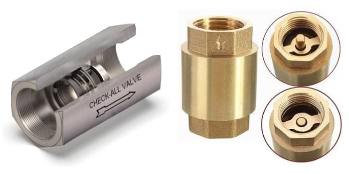
These valves are easy to operate, maintain and have simple design, see figure 3. Where, A is valve body, B is disc, C is spring and D is guide. As, the pressure at the inlet side of the valve exceeds the cracking pressure, the disc gets pushed that creates an opening and the fluid is allowed to flow through the valve. If the pressure at inlet decreased below the cracking pressure or the pressure at outlet exceeds the resealing pressure, the disc moves in reversed path by the help of spring force and closes the opening to prevent the backflow of the fluid. This valve is also design to take care of the pressure surge in the pipeline therefore it also safeguards the pipeline from hammering effect.

2. Spring Loaded Y Check Valve: ( Types of Check Valves )

Spring Loaded Y Check Valves
Spring Loaded Y Check Valve

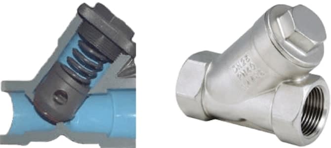
The figure 4 shows the typical illustration of spring-loaded Y check valve. Its operation is similar to the in-line check valve but there is only one difference, that is the disc is placed at an angle to the fluid flow direction. This change enables the check valve to inspect and maintain while the valve connected to the pipeline. But, because of its shape, it takes more space than the in-line valve.

3. Ball Check Valve: ( Types of Check Valves )

Ball Check Valve
Ball Check Valve

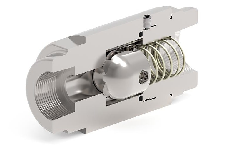
The ball check valve either be spring loaded or free-floating type. As the cracking pressure for spring loaded valve is more than that of free-floating ball valve. Thus, the free-floating type is used for low pressure application and the spring-loaded type is used for high pressure application. The figure 5 shows illustrations of spring-loaded ball check valves. Its working principle is also similar to the in-line check valve, but instead of disc, a ball is used for the purpose.

4. Diaphragm Check Valve: ( Types of Check Valves )

Diaphragm Check Valves
Diaphragm Check Valve

It consists of a rubber diaphragm that flexes inside the valve to open or close the passage. The figure 6 shows schematic diagram of a diaphragm check valve. Because of the diaphragm, there is very low or no cracking pressure possessed by the valve. As the pressure at inlet increases the diaphragm flexes more and the size of passage increases accordingly. In case of any backflow, the diaphragm is forced against the opening and seal the passage to prevent backflow. These kind of check valves are ideal for low pressure or vacuum application.

5. Lift Check Valve: ( Types of Check Valves )

Lift Check Valve
Lift Check Valve

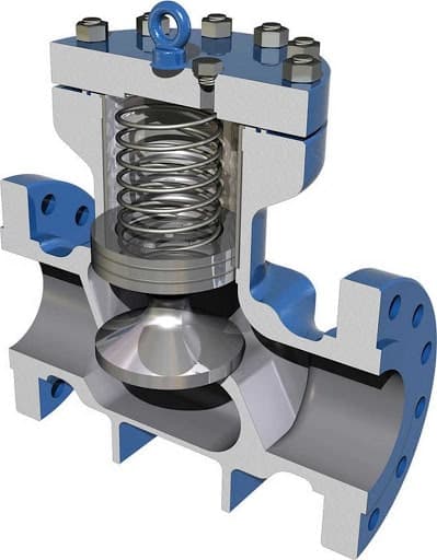
It consists of a spring-loaded disc that lifts off when the pressure at inlet exceeds the cracking pressure and allow the fluid to pass through the valve, as shown in figure 7. As, the pressure at inlet decreases less than the cracking pressure or there is any backflow in the system, the disc reverses its movement by the help of spring force and closes the valve opening. Instead of spring, gravity assisted disc movement is also incorporated in the valve sometime.

6. Swing Check Valve: ( Types of Check Valves )

Swing Check Valve
Swing Check Valve

This check valve is also known as tilted disc check valve. It consists a disc that is hinged radially on one side. As the pressure at the valve inlet port increases, the disc swings about the hinge and opens the passage for fluid flow. In case of back flow, the disc swings back to initial position and completely closes the passage. There is no spring used in this valve and the movement of the disc is completely relies on the gravity. Figure 8 shows a swing check valve for instance.

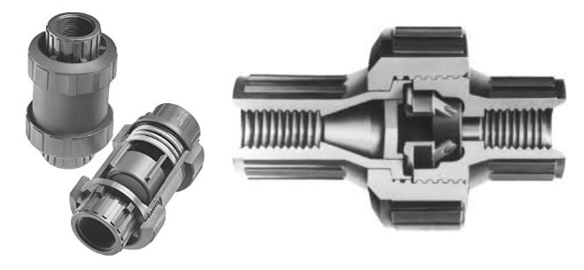
7. Duckbill Check Valve: ( Types of Check Valves )

Duckbill Check Valve

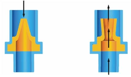
This check valve uses a soft tube that changes its shape according to the flow direction and hence, ensures the unidirectional flow of fluid inside the valve. If fluid is flowing in forward direction, the end of the soft tube changes its shape into diverging type and allowing the fluid to pass easily. As, the fluid reverses its direction, the end of the soft tube becomes converging and restricts the fluid to enter into it, see figure 9.

8. Wafer Check Valve: ( Types of Check Valves )

Wafer Check Valve
Wafer Check Valve

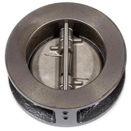
The wafer check valve consists of a wafer style disc that is hinged on one side, assisted with the spring, as seen in figure 10. If there is backflow occurs in the system, the wafer flips and cover the passage.

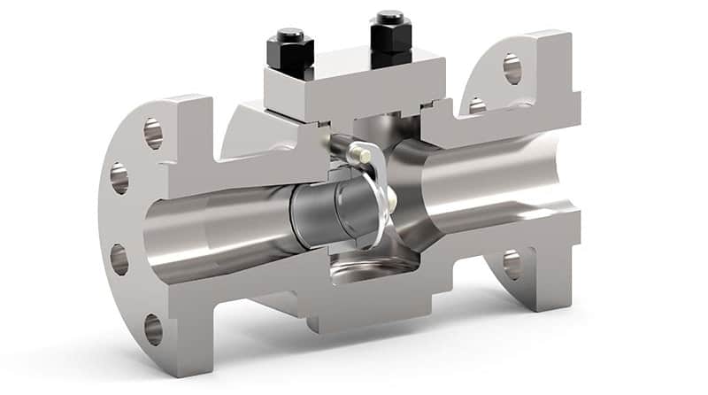
9. Stop Check Valve: ( Types of Check Valves )

Stop Check Valve
Stop Check Valve

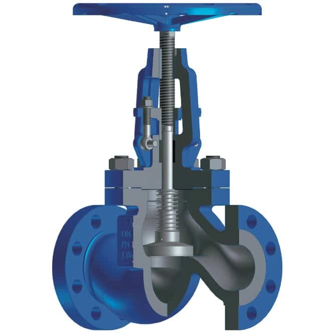
The stop check valve is basically a lift check valve or Y check valve with spring assistance. This valve has manual override feature which allows it to, apart from functioning as normal check valve, override and maintain the valve in open or closed state. Thus, this valve can be used for two features at a time. To perform the override actuation ids generally given by manually through a lever or wheel, as shown in figure 11. This type of valves is generally used in power generation plants, specifically in steam generators, turbines and safety accessories.

10. Foot Check Valve: ( Types of Check Valves )

Foot Check Valve
Foot Check Valve

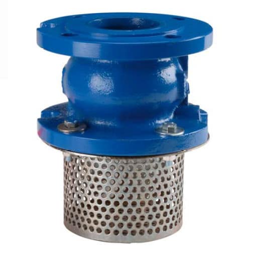
In this type of valve the inlet port is not available, instead, a strainer is available in place of the inlet port, as shown in figure 12. It is basically an in-line ball check valve with spring assistance. This helps the valve to maintain or allow the flow only in one direction whereas block the passage in reverse direction. The strainer available at the inlet prevents the debris and sand particles to enter into the check valve which may cause damage for the check valve as well as the fluid flow system. It is generally installed at the end of the pump suction line of a fluid flow system.

The materials used to manufacture the different types of check valves are generally stainless steel, brass, poly vinyl chloride (PVC), polypropylene (PP) etc. The selection of valve type and its materials depends upon following factors: –

  1. The compatibility of the material with the flowing fluid.
  2. Size of the pipeline and space available.
  3. Requirement of cracking pressure and reseal pressure.
  4. Installation direction; horizontal or vertical.
  5. The dimension and shape of the envelope.
  6. Accessibility for the inspection, maintenance and repair.
  7. Temperature of the flowing fluid as well as working environment.

Applications of Check Valve

On the basis of work function of the check valves, it can be used for following different applications;

  1. To prevent the backflow of fluid creating damage to the system.
  2. To ensure the prevention of contamination due to backflow of the fluid.
  3. To avoid the siphoning action in a pipeline.
  4. To maintain the vacuum seal.


TYPES OF PULLER


Types of Puller

Types of Puller :- A puller is a tool used to remove sets from the rotating machine shaft. The most common application of puller is removing a caped set of ball or tapered bearing from a rotating shaft. For example In car transmission pullers are made up of steel of tool grade. While tool grade is harder than the parts they are used on.

Types of Puller
Type of Puller

Generally these pullers are hand powered with a handle to turn the screw. Some are powered hydraulically using hydraulic power piston to press against the end of shaft the bearing is on.

These pullers are also comes within small variety in sizes to remove the (mm) size bearing. These are arms with extension that gives slight edge to user for pulling bearing easily during the operation.

Main components of puller

Some main parts of the pullers assembly are listed below:

  1. Hexagonal head on bearing puller – hexagonal head is attached to the forcing screw. It is fixed with socket wrench for rotation with ease.
  2. Bearing puller forcing screw – forcing screw is long & fine threaded screw that is rotated corresponding to the shaft. When they force is applied to the screw to produce force that is transmitting to the components that we are removing.

  3. Bearing pullers cross arms – the cross arms attaches the legs to forcing screw.

  4. Reversible claw legs on a bearing pullers – legs allows internal & external pulls.

Types of puller

These pullers include bearing splitter plates, 2 and 3 arms bearing pullers, internal bearing pullers, bar type puller &slide hammer puller.

1. Bearing splitter plates

 Bearing splitter plates are safest types of bearing pullers to use. From technically point of view they are actually not puller as they uses the mechanism of pushers, they tends to push and pop ( meet or fixed) with the shaft.

Bearing splitter plates

Bearing splitters plates mainly consist of two plates held together with respective to their large diameter, heavy nut with good duty screwed with the help of nut on the all 4 ends.

2. 2& 3 arms bearing puller

2& 3 arms bearing puller

These are one of the most common types of pullers to extract (removal) of bearing sets or gears. Arms having fingers on the end that bend to get behind the bearing. The center screw of the puller is torqued so it pushes on to the top of shaft & upward thrust is applied to the bearing. Arms and fingers are reversible so same puller can accommodate the wide variety of bearing & shaft sizes, length.

3. Internal bearing puller

Internal bearing puller

Internal bearing pullers are made up to extract bearing set. These are generally favorable in condition of small dent puller. They have a slide hammer with shaft to act thrust upward &shock to the bearing. Collet is the part that went into the bearing at the tip of puller shaft is expandable.

4. Bar type puller with bearing separator

Bar type with side rod threaded into bearing separator provides knife edge to get behind components or when there is not good gripping edge at all.


TYPES OF WRENCH


Types of Wrenches & Their Uses [with Pictures]

Types of Wrenches & Their Uses [with Pictures]
Types of Wrenches

What is Wrench?

Types of Wrenches & Their Uses [with Pictures] :- A wrench is also termed as a spanner tool which is used to provide grip as well as mechanical advantage while applying torque to turn the objects. These are the mechanical devices which are used for turning the objects. There are various types of wrenches which are discussed in detail below. Scroll down to know more.

31 Different Types of Wrenches

1. Socket Wrench: ( Types of Wrenches )

The socket wrench is also termed ass a ratchet which uses a ratcheting mechanism in order to allow quick tightening or loosening the nuts or bolts without removing the wrench from the fastener. This is the type of wrench which is available with some of the most common sizes like 1/4″, 3/8″, 1/2″, and 1″ drives amongst which you can fit the most appropriate size of socket depending upon the requirement of your site.

In case there is any obstacle found during turning the handle, then you can immediately reverse the course in order to save the object from being damaged and to continue working.

2. Pipe Wrench: ( Types of Wrenches )

Pipe wrench is referred to as that spanner which is used to fasten or dismantle any type of pipes and their fittings. The jaw of this type of mechanical devices is made up of forging tough steel. Its movable jaws are found having flat threads which are cut and on its fixed jaw, the plate is joined with a groove which is present inside it.

A knurled round nut is also installed in this type of groove. By revolving this nut, the movable jaw either increases or reduces the size by movement either upwards or downwards. Here, a spring is also fixed within the fixed and movable jaw in order to give a proper grip of the job. The pipe wrenches are usually found in the sizes 6”, 9” and 18”.

3. Ratcheting Wrench: ( Types of Wrenches )

The ratcheting wrench is found to be quite similar to the combination wrench. This wrench has at least one end inside which is a ratcheting device and allows the user to turn the wrench in order to tighten or loosen without removing or adjusting the position of the wrench handle hits an obstacle after each turn. This feature helps in easy working in the areas with less space.

4. Chain Wrench: ( Types of Wrenches )

Chain wrenches are used in order to fasten or dismantle the pipes or round jobs which are mostly of the larger diameter. Whenever the job is held in the wrench it gets revolved easily. Making of a chain wrench includes of a plate which has cuts in its mouth and is then installed and joined with a rivet. The chain drips is used to make the job very strongly.

5. Torque Wrench: ( Types of Wrenches )

Torque wrenches are the types of wrenches which are manufactured to give a certain amount of torque without overtaking or tightening. This wrenches are used for any automotive work for tightening the wheel lug nuts. A torque wrench can also be used on bicycles, farming equipment or any other site where there is a requirement of tightening the nut or bolt to a particular torque specification which is usually determined by the manufacturer.

6. Oil Filter Wrench: ( Types of Wrenches )

The oil filter wrench is referred to as that which is actually of four different styles and is used primarily in the automotive industry. The chain strap along with the metal strap style filters apply a loop in order to protect the filter casing. There are socket-style filter wrenches which resemble with a cup and consists of chopped parts. These wrenches fit under a filter cap which are used with a ratchet handle.

7. Combination Wrench: ( Types of Wrenches )

The combination wrench is referred to as those which consists of a closed-loop at one end for hexagonal or square nuts and an open U-shape loop at the other end. These types of wrenches are usually used for hard nuts in order to quickly finish the job. Sockets can be one example of a combination wrench which is mostly sold in a kind of wrench sizes.

8. Adjustable Wrench: ( Types of Wrenches )

Adjustable wrenches are the ones which are found having an open end accompanied with a spiral screw which is fixed and opens or closes the crescent one the user turns it. Adjustable wrenches are one of the most common types of wrenches which are easily available in the market and also used by most of the workers. These types of wrenches are also termed as a crescent wrench as it can perform the same basic function as a whole set of combinations or open-ended wrench, but it needs more area as it is found to have bigger size.

9. Impact Wrench: ( Types of Wrenches )

The impact wrench is referred to as that wrench which uses an air compressor while the cordless impact wrench utilizes the rechargeable battery. This type of wrench are also termed as an air wrench or air gun which is used for resembling a cordless drill.

This wrenches are the ones which uses a high torque in order to remove stubborn nuts or bolts. These devices are a great option for handling many nuts whereas they are a bad selection for any job which requires high accuracy.

10. Crowfoot Wrench: ( Types of Wrenches )

Crowfoot wrenches are referred to as those wrenches which do not have handles and are therefore termed as open-wrench. The single head is built which can be attached to a ratchet handle or any socket extension which can allow it to fit in really tight positions.

In case the user does not wish to remove the surrounding parts, they can do a lot of work in handling the bolts which are located deep on the body of the machine.

11. Pedal Wrench: ( Types of Wrenches )

The pedal wrench is referred to as the wrench which consists of a round tip, usually with one or two U-shaped recesses. These types of wrenches are usually used in the repairing work of the pedal. So, these are most commonly used in bicycle repair shops or a pedal boat.

12. Monkey Wrench: ( Types of Wrenches )

Monkey wrenches are quite similar to an adjustable spanner. The difference is that these wrenches are found having bigger jaw which is built with a handle itself. The other jaw is found to be movable on which the threads are cut as that in the pipe wrenches. The jaw of such plain surfaces is similar to that of an open-end spanner. These wrenches can be adjusted along with a round nut which is also used as a screw wrench.

13. Pliers Wrench: ( Types of Wrenches )

A plier wrench is referred to as the one which consists of flat-edged jaws and are at an angle which is attached to a handle and is joined by a bolt.  A bolt slide within two or more positions of an opening on the upper jaw, provides the wrench which needs to be arranged in order to fit in various sizes of heads. The name of this type of wrenches is evolved from the way this tool is gripped and is quite similar to that of a pair of pliers.

14. Strap Wrench: ( Types of Wrenches )

Strap wrenches are used whenever there is need for holding pipes or any round object. This is the reason these wrenches are used whenever there is any damage caused. There is a leather or canvas belt which is provided and is rolled around the job and tightened with the buckle. Other than this there is a handle with the help of which the pipe is revolved.

15. Plumbers Wrench: ( Types of Wrenches )

Plumber wrenches are quite similar in the design of the plier’s wrench. The jaws of the plumber wrench are shaped like that of a hexagonal nut which are adaptable to fit various types of pipe fittings. These types of wrenches are particularly used in the plumbing work on pipes and fixtures.

16. Tap Wrench: ( Types of Wrenches )

The tap wrench is referred to as a wrench which is similar to a key that fits the square drive of the tap and is used to cut the female thread like the inner portion of the nut. These are the wrenches which can be T-shaped or can have a double-handle bar with an attachment socket in the middle.

17. Spud Wrench: ( Types of Wrenches )

The spud wrench are referred to as those wrenches which has fallen out of common use at the opposing end used to line the holes on the pipes. It has since been rendered obsolete by the plumber’s wrench which can also be found in the occasional toolbox.

18. Alligator Wrench: ( Types of Wrenches )

An alligator wrench is referred to as that wrench which is found having a serrated top jaw, whereas the rear is smooth. The alligator wrench was mostly identified due to the way it gripped the nuts.

The handle of an alligator wrench is quite similar to a pointed fang than a modern pipe wrench because most of these were primarily manufactured in order to handle square-shaped heads, whereas now it has become rare to see them in the real life.

19. Basin Wrench: ( Types of Wrenches )

Basin wrench is a type of wrench which consists of a long T-shaped handle in a curve along with a serrated jaw. The main purpose of these types of wrenches is to tighten or loosen the heads under the sink and toilet. These wrenches are consequently also termed as faucet wrench.

20. Armorer’s Wrench: ( Types of Wrenches )

An armorer’s wrench is referred to as a single-piece wrench which consists of a C-shaped, serrated head and involves a square slot or a hole in order to attach the ratchet handle. These type of wrenches are available in various designs and are usually of the specific type or size of the model. The main purpose of an armorer wrench is for gun repairing and its maintenance.

21. Dog Bone Wrench: ( Types of Wrenches )

Dog bone wrenches are the wrenches which have two box-shaped ends with a different socket size. This wrench was named in such type due to its bone-shaped appearance, which was sometimes also termed as the dumb-bell wrench.

These types of wrenches are only used in the case of bike maintenance, although their ability to fit in the small spaces sometimes makes them quite useful. There are some dog bone wrenches which are found having swivel heads that serve greater flexibility.

22. Drum Key Wrench: ( Types of Wrenches )

A drum key is the type of wrench which is also termed as square-holly socket wrench and consists of T-shape along with a flattened handle.

According to the name, these are the types of wrenches which are mostly used to tune various percussion instruments like drum. It is important to know that a drum key with longer handles provides the user to apply more torque as compared to the shorter handles.

23. Bung Wrench: ( Types of Wrench )

A bung wrench is referred to as a wrench which is similar to a socket-style wrench and is available in a variety of styles. These types of wrenches are quite similar to drum plug wrench. These are the types of wrenches which are specifically manufactured in order to eliminate the plastic or metal dung on a drum or barrel.

24. Fan Clutch Wrench: ( Types of Wrench )

Flat clutch wrenches are referred to as those wrenches which consists of a U-shaped opening at one end. These types of wrenches are specially designed to remove fan clutches from the cars.

At the other end of such wrenches there is a square opening which is useful in providing them double efficiency as a clutch hold tool, whereas a second wrench is used to turn the hex nut.

25. Cone Wrench: ( Types of Wrench )

Cone wrenches are referred to as the wrenches which are found to be wide and flat and are used on the conical parts of a cup and cone hub. These types of wrenches are used to accommodate the levelling feet of a bicycle or washing machine whereas it is sometimes used on the other gentle projects where a typical open-ended wrench is found to be quite thick.

26. Hammer Wrench: ( Types of Wrench )

A hammer wrench is a short and thick wrench which is found having a block end and is used to strike along with a hammer in order to transmit a greater amount of force. These types of wrenches are also termed as striking wrenches and are used to tighten almost all the large flange fittings and fasteners. A hammer wrench is also used to free the rusted nuts and bolts by applying higher amount of force. These types of wrenches are therefore termed as heavy-duty wrenches which are used in some metal, plumbing or electrical jobs.

27. Torx Wrench: ( Types of Wrench )

The Torx key wrenches are referred to as those wrenches which are manufactured to fit into the star-shaped head of any type of bolts and screws. These are also known as a star-headed key and can be bought in the same L-shape and the user can also buy these in a laid-back set which resembles in shape as a Swiss Army knife than a wrench set.

28. Garbage Disposal Wrench: ( Types of Wrench )

There are various models which are found with a larger type of Allen wrench and are used to remove the clogs. Therefore, here comes the need of a garbage disposal wrench which is used to execute such missions without any inconvenience. There are two types of wrench which are commonly used for the clogged waste disposal.

In order to handle larger nuts there are various other types of flat wrenches with a squat, and U-shaped pivoted head. These are also used to dislike the clogs in cutter variants which is exactly similar to the Allen variants.

29. Spoke Wrench: ( Types of Wrench )

The spoke wrench is referred to as that wrench which is observed to be small in size. These are the type of wrenches which are designed in order to maintain the spokes on the wire wheels. These wrenches are found having two different ends wherein one end consists of a slot which fits around the spoke whereas the other end has a drive head that fits around the nipple nut.

The spoke wrench can be rotated in a complete cycle even without removing it, with respect to its size and shape. The perfect place where these types of tools can be found is a bike repair shop. There are some changes which are quite similar to a small open wrench whereas on the other hand there are some which look more like curved as well as flat metal.

30. Tension Wrench: ( Types of Wrench )

A tension wrench is referred to as the key element in the lock and is found to be available in a very broad range of designs. These types of wrenches can be either hard or soft and can also be used to apply tension whereas the pick keeps on doing its job.

31. Spanner Wrench: ( Types of Wrench )

The spanner wrench is referred to as that wrench which is a sort of special and specific class of equipment which is found having a curved end which can easily resemble either a hook or C-shape.

Mostly these types of wrenches are found consisting of pins which permits them to be used on either a wide variety of objects that vary from spanner head screws to the retainer rings. The spanner wrench is a hand-held tool which is widely used to provide grip and to either tighten or loosen the fasteners.


TYPES OF THREADS


Types of Threads: Definition, Parts and Thread Identifying Tools [with Images]

Types of Threads: Definition, Parts and Thread Identifying Tools [with Images]
Types of Threads

Definition of Threads

Types of Threads: Definition, Parts and Thread Identifying Tools [with Images] :- Thread are found having a very critical role in the engineering line specifically for manufacturing various items of day to day life. In the manufacturing industry the machines are used almost at every moment and without threads, almost all the machines are incomplete. Talking in the technical language the spiral grooves of equal measurement or shapes made up of a round cylindrical article or pipe are referred to as threads or in other words, spiral grooves of equal pitch and equal depth which is made on the parallel round cylindrical surface or conical round surface is referred to as threads.

Main Parts of Threads

Generally there are three main parts of the threads are following:

  1. Shank Diameter
  2. Thread Per Inch ( TPI)
  3. To The Point

1. Shank Diameter

Shank diameter is represented by the diameter of the thread as the number goes higher so as the diameter of the threads. Shank size will decide which screw threads is most compatible or ideal with for the specific job.

2. Thread Per Inch ( TPI)

It is generally abbreviated as TPI. This is simply the no of threads found or designed in an inch (1”). Low TPI likes of 7 &8 represent the coarse screw while 18 or 22 provides the fine screw threads for metal fastening.

3. To The Point

The most common types of screw points are self piercing point & self drilling points.

Self Piercing Point :- it has such sharp point designed to cut through the material as the screw thread.


Self Drilling or Drilling Points :-  it is equipped with drilling feature at the tip of the screw that is used to bore a hole through the metal before thread engages to fasten the pieces together.

How to Identify Different Types of
Threads?

Before you start, make sure you have two thread identifying tools on hand;

1. Pitch Gauge

A pitch gauge is referred to as an instrument which is used to measure the distance within the crests of threads. For NPT, UN/UNF, BSPP and BSPP the number of threads per inch are measured. In case the observer has the metric threads, then the pitch gauge would identify the distance within each individual crest in millimeters.

2. Caliper

A caliper is referred to as that instrument which is used to measure the diameter of a thread. For the male threads, it is found measuring just the outside diameter whereas for the female thread it measures the inside diameter. For all the advanced users, there is a digital caliper which is available in the market which saves the time and also simplifies the process.

Thread Identifying Tools

A) Difference Between Tapered Thread & Parallel Thread

Parallel Thread & Tapered Thread

There are various types of threads, so it important to know all the types of threads along with their features and applications so that while using these instruments a correct type can be selected by the user. Scroll down to know more about the types of threads.

Parallel threads are the threads which include:

  • UN/UNF
  • BSPP
  • Metric parallel

Tapered threads are the threads which include:

  • NPT/NPTF
  • BSPT
  • Metric tapered

In order to identify whether the thread is tapered or parallel one can have a look at the diameter of the thread. In case the thread diameter is found being thinner towards the end then it is confirmed that it is a tapered thread. Whereas in case the thread diameter is found to be same at the top as well as the bottom of the thread then it can be termed as a parallel thread. There is one more way by which you can find out whether it is a parallel thread or tapered thread, if the threads touch the entire length of the calipers then it is surely a parallel thread otherwise it is a tapered thread.

B) Determine the Size

An instrument known as thread pitch gauge tool should be used in order to determine the size of the thread. The thread pitch gauge helps you in accurately measuring and calculating the number of threads within a required distance.

C) Size of the Thread

Whenever it comes to determine the actual size of the thread one should have two approaches. Before starting one must determine whether your thread is a pipe thread (NPT/NPTF, BSPT, BSPP) or not (UN/UNF, Metric Parallel, Metric Tapered). One must note that the tapered thread can be a pipe thread. In case you are found having pipe thread then you can compare the size of the thread with a nominal size profile. If you are working for non-pipe thread (UN/UNF, Metric Parallel, Metric Tapered) then you must use the caliper tools in order to measure the outside diameter of the thread.

4) Designated Thread

These are the steps which involve a designating thread according to the industry standards for further use. Start with identifying the thread size and then note the type and pitch.

13 Different Types of Threads

While coming to types of threads most of the people who work in the industry can recognize the types of threads as almost all these types are used in the industries. Mainly the threads and connections are divided into six types which are as follows:

  1. UN/UNF
  2. NPT/NPTF
  3. BSPP (BSP, parallel)
  4. BSPT (BSP, tapered)
  5. Metric parallel
  6. Metric tapered

There are following 13 different types of threads which are as follows:

  1. Left-Hand Threads
  2. Right-Hand Threads
  3. Taper Threads
  4. “V” Shape Threads
  5. Metric or International Threads
  6. British Standard Threads
  7. Seller Threads
  8. Square Threads
  9. Acme Threads
  10. buttress Threads
  11. Worm Threads
  12. Knuckle Threads
  13. Single and Multi-Threads

1. Left Hand Threads: ( Types of Threads )

Left hand threads are referred to as those threads which are inclined towards the left hand. These are the ones which are fixed in an anticlockwise movement. For instance threads on a screw with left-hand threads, which are so cut that the bolt, screw or nut have to be turned in a counter-clockwise motion to tighten it. These are the types of threads which are used quite rarely.

2. Right Hand Threads: ( Types of Threads )

Right hand threads are referred to as those threads which are inclined towards the right-hand side. These are fixed in a clockwise movement which are also referred to as right-hand threads.

3. Taper Threads: ( Types of Threads )

Taper threads are the threads which are found having a cut around the taper surface and is thus named as taper thread. These are the threads which can be either right handed or left handed.

The usage of the taper threads are as follows:

  • In order to join two or more parts of a machine like nut-bolt and stud.
  • In order to get mechanical livers for lifting weights like chain pulleys, jacks etc.

  • For higher accuracy in precision instruments like micrometers.
  • For jobs of power transfer.
  • In order to control or minimize the speed.

4. V-Shape Threads: ( Types of Threads )

V-shape threads are the type of threads which is found in the shape of an English alphabet V. These are the types of threads which are most widely used and can be cut or made by tap, die, lathe machine, milling etc. These threads are found to be made up of various standards.

5. Metric or International Threads: ( Types of Threads )

Metric or international threads are the types of threads which were originally adopted in the year 1898 to 1908 in central France. As the usage increased all the other international countries also started using it. However, the Indian standard institute has also adopted this thread so far.

These are the threads which are made on an angle of 60°. The screw of these type is flat and the root is found to be round. As per the I.S. 1330-1958, the number of threads is 20 per inch and its pitch is 2.5 mm.

6. British Standard Threads: ( Types of Threads )

A) British Standard Whitworth Threads

British standard whit worth threads are the types of threads which was originated from the great Britain and was named after Sir Joseph Whitworth who was a renowned citizen of Great Britain who invented this thread in the year 1841. This is the thread which was used to provide the facility of interchangeability and is used in ordinary nut-bolts and various other jobs. The angle of these threads is 55° and its crest along with the roots are in round shape. These threads are also termed as B.S.W. Thread.

B) British Standard Fine Threads

British standard fine thread are the threads which are quite similar in shape to B.S.W. threads. The angle of this thread is also same as that of BSW thread i.e. 55°, whereas the number of thread per inch is more which means that the thickness of the thread is less. This in turn is responsible for making the grip stronger. Nut bolts comprising of this type of threads are used where is more vibration.

C) British Association Threads

British association threads are the type of thread which is used in small or tiny electrical and mechanical instruments like radio, television, electrical goods, meters and watches. The angle of these types of threads is 471/2° which can easily be used for 1/2″ or 6 mm nut bolts.

D) British Standard Pipe Threads

British standard pipe threads are found having an angle of 55° which cuts at 3/4 taper per foot. These types of threads are used in sanitary pipe fittings, steam pipes, gas pipelines as due to the taper, it does not leak.

7. Seller Thread: ( Types of Threads )

Seller threads are the type of threads which are known by its name of American national thread. These have been recognized by the American standards institute and is a type of V shape thread. These threads are found having an angle of 60° and also have flat roots and crest. The same standard institute was responsible for inventing the national fine thread which is a quite thin thread. These are the threads which are mostly used in the motor vehicles as well as the airplanes.

8. Square Thread: ( Types of Threads )

Square threads are referred to as those threads which are found having very powerful root. It is named in such a way as it is found making the square and these are the threads which are used for lifting heavy loads, transfer of power, exerting pressure, and screw jack and vice spindle instruments. The specific measurement or number per inch of such threads are not particular.

9. Acme Thread: ( Types of Threads )

Acme threads are referred to as those threads which are more or less similar to square threads whereas their shape is in taper like the flat from bottom and thin from the top. In comparison to square threads these are easier to cut it on a job and are also considered stronger. These threads are found having slanting ends and therefore are easier to fix or unscrew the split nut on it but do not have a backlash in it.  Acme threads is made up at an angle of 29°.

10. Buttress Thread: ( Types of Threads )

Buttress threads are referred to as the screw threads which has a triangular section but also has one face at the right angle of the axis of the screw and the second face only being sloped. These are the threads which are found having more pulling power as compared to the square thread. This is the only reason why these are used in cases where there is an excessive pull required on one side and which can must be absorbed.

11. Worm Thread: ( Types of Threads )

Worm threads are referred to as those threads which are found to be almost similar to the acme threads whereas are found to be deeper as compared to the acme threads. The angle of worm threads is found to be 29 ° and are named in such a way as they are used in worm wheels of motor vehicles in order to transfer the power at an angle of 90°. As soon as the three teeth of the worm wheel gets fitted into the shaft along with the worm thread, they get properly installed.

12. Knuckle Thread: ( Types of Threads )

Knuckle threads are referred to as those threads which are also quite strong and are used in heavy and light jobs of rough nature. These are the threads which are found having half round at both the root as well as the crest. These threads can also be casted in a mold.

13. Single and Multi-Thread: ( Types of Threads )

Considering a particular piece of work, it is possible to have various types of threads which are found running along with it. Therefore, here are single-threaded screws and multiple or multi-start threaded screws which are important in various piece of works and are highly used. The independent threads are also termed as starts which are found having a single-start, two-start, three-start, etc.

As soon as one turn is completed, round the screw or bolt then there is a movement of one thread wherein the screw is referred to as a single-threaded screw and once there is a movement of more than one thread, the screw can be referred to as a multiple or multi-start threaded screws.


Now considering the case of a three-start thread, in one complete turn, then the thread gets advances three times as far if it is considered as a single thread. Multi-start threads are referred to as those which are used in those cases wherever there is a fast movement or motion required fountain these are the places which are used widely.


TYPES OF EVAPORATOR

Types of Evaporator and Their Applications [with Pictures]

Types of Evaporator and Their Applications [with Pictures]
Evaporator

Types of Evaporator and Their Applications [with Pictures] :-

Types of Evaporators

1. Falling Film Evaporator: ( Types of Evaporators )

Falling Film Evaporator

Falling film evaporators are made up of 13 ft to 26 ft tubes which is enclosed with the steam jackets. Falling film evaporators require uniform distribution of solution. The solution in this evaporator enters from top from where distributor distributes it evenly to every tube. In this evaporator, as the solution flows downward it gains velocity due to the gravitational pull. As the vapour developed gradually in response to the heating medium, the velocity increases as well. Falling film evaporators are used for high viscous solutions therefore they are usually used for sugar, chemical, fermentation and food industries.

Application of Falling Film Evaporator

Falling film evaporator are used for sugar solution, black liquor, concentration of dairy products and phosphoric acid

2. Forced Circulation Evaporator: ( Types of Evaporators )

Forced Circulation Evaporator

These evaporators are also known as natural circulation evaporator and these evaporators are generally based on natural circulation which is the result of the difference in density which arises due to the heating. Due to the use of tubes when water starts boiling then it results in rise of bubbles which leads to the circulation and thus separates the vapour as well as the liquid at the top of heating tubes. Evaporation amount directly depends on temperature difference between solution and the steam.

The main problem with forced circulation evaporators arises when the tubes of evaporator do not completely immersed in solution and this will create compromised circulation and dried out system. To overcome this problem, circulation are achieved with the help of inserting a pump for increasing the circulation as well as pressure. This type of circulation generally takes place when the hydrostatic head restrict the boiling at heating surface.

Forced circulation evaporators are generally used in waste streams, viscous fluids, crystallizers and various of difficult process fluids, the suppressed boiling can helps in reducing the fouling and scaling. Pump can also helps in reducing fouling which is caused by liquid boiling on tube because the pump can reduce the formation of bubble. Few other problem in the forced circulation evaporators are undefined residing time and high consumption of stem but for high temperature it is easy to achieve good circulation.

Application of Forced Circulation Evaporators

Forced circulation evaporators are used for sodium sulphate, citric acid, urea, sodium chloride, caustic potash, ammonium sulphate and magnesium chloride.

3. Climbing and Falling-Film Plate Evaporator: ( Types of Evaporators )

These evaporators have generally larger surface area. The plates are generally supported with the help of frame and are corrugated. At the time of evaporation the steam will flow through the free space channels which are in between plates, steam climbs and then fall parallel to the liquid which is concentrated. In relation to liquid, the steam will follow counter current path. The vapour as well as the concentrated liquid is then sent to separation stage in which vapour is sent to the condenser. Due to the spatial flexibility this evaporators are generally used for fermentation and dairy industries. The disadvantage of this evaporator is that their ability is limited in treating solid containing and viscous products.

Application

Climbing and falling film plate evaporator are used in dairy industries.

4. Rising / Falling Film Evaporator: ( Types of Evaporators )

Rising Falling Film Evaporator

This evaporator are combination of a falling film evaporator and the rising film evaporator therefore it provide the advantage of both the evaporators. These are used for high ratio of evaporation with feed, and the bundles of tube are segmented in two different parts, in which first part are operated as rising film and second part are operated as falling film.

Application

Rising/ Falling film evaporator are used for handling of foamy liquids or liquids in which there are high evaporation load.

5. Rising Film / Long Tube Vertical Evaporator: ( Types of Evaporators )

Long Tube Vertical Evaporator

In this evaporator boiling occur in the tubes because the heating is done outside the tubes generally by steam. Therefore submergence is not required. These evaporators are generally efficient but the major disadvantage is that scaling occurs quickly in the internal surface of tubes. So, this evaporator is suitable for non salting and clear solution. Tubes in this evaporator are generally long which can be more than 4 meters. Deciding the size of the evaporator is difficult because it need precise calculation of level in process liquid in tubes.

6. Agitated Thin Film Evaporator: ( Types of Evaporators )

Agitated Thin Film Evaporator

It is very useful for the products which is difficult in handling. These evaporators are able in the separation of volatile component from the components which are less volatile with the help of mechanical agitation and indirect heat transfer of flowing product film in control condition. This separation is done in vacuum condition for maximizing the change in temperature with maintaining temperature which is favorable for product. There are some technical issues occur at the time of evaporation.

There are few evaporators which can be sensitive to viscosity difference as well as consistency of dilute solution, these evaporators results in inefficient work due to the circulation loss. When high viscous solution is needed to be concentrate then evaporator’s pump are changed.

Fouling in evaporator takes place when stiff deposits create surface on the heating medium of evaporators, it occurs in case of proteins, food and they ultimately decrease the heat transfer efficiency.

Application of Agitated Thin Film Evaporator

Agitated thin film evaporators are commonly used for purifying organic chemicals which include insecticides, natural oils, herbicides, fatty acids. Pharmaceuticals and food concentration which include biological solution, fruit purees and vegetable purees, vegetables and plant extracts etc.

7. Multiple Effect Evaporator: ( Types of Evaporators )

Multiple Effect Evaporators
Multiple Effect Evaporator

These evaporators are manufactured of seven evaporators effects/ stages. The requirement of energy for single effect evaporators are huge and are responsible for most of the cost of evaporation system. By putting seven evaporators effects/ stages together can save the heat requirement therefore need less energy. By providing one evaporator to the existing original one results in reduction of energy consumption by 50 percent, and further addition of a evaporator will reduce the energy consumption by 33 percent. There is a heat saving percent which is used for the estimation of how much energy is saved with the addition of a particular number of effect. Generally in multiple effect evaporators, the number of effects are kept to seven because at seven effect the equipment cost will reach to cost saving.


STEAM TURBINE STANDARD OPERATING PROCEDURE

Steam Turbine standard operating procedures (SOPs) Lube oil system operation Pre-checks • Ensure lube oil tank level is normal • Ensure l...