 Hydrostatic head or Hydrostatic pressure
The height of the strike
The massecuite circulation will be slow down
while massecuite reaching level 1000 mm above the top tube plate.
Generally, the highest massecuite level above
top tube plate is kept around 1000 mm to 1200 mm in batch pan and 300mm to 500
mm in continuous pans without using any mechanical circulator. While using the
mechanical circulators, it will be increased by 200 to 300 mm height
Bottom Cone
The bottom of the pan generally takes the
form of a truncated cone, but a segment of a sphere, or even a torus may be
followed.
This part of the pan is situated at the
bottom of the pan below the calendria making an angle of 170 to 250 with
the extended portion of the vertical side wall of the calendria.
The extended portion is of about 150mm to 200mm.
This is to facilitate the repairs /
replacement of the end tubes of the calendria. It is advantageous for graining
volume that these angles should be small but, for rapid flow of the massecuite
at the moment of discharge, an angle of less than 17° will not generally be
used.
Generally, cone angle is 180 to 200 is the
value while considering all advantages and disadvantages
Downtake Diameter
The downtake diameter is generally not less
than 0.4 times the pan diameter, unless a stirrer is fitted. A smaller diameter
has been shown to restrict circulation.
Circulation ratio is one of the important
criteria for estimating the downtake diameter.
Ideally this should be less than 2.5 to
obtain a pan with good circulation, although a number of pans that have
circulation ratio values up to 2.8 have given reasonable results.
Tubes
Generally the tubes are made up of Stainless
steel. The diameter of the tube is 100 mm and length of tubes varies from
700-1500 mm.
Stainless steel for tubes is generally AISI 304 grade (18% Cr + 8% Ni).
The tubes are generally, 100 mm diameter and
installed on triangular pitch. The legment having 16 mm.
Tube diameters may be for low grade and
smaller for high grade massecuites.
Boiling Point Rise
The boiling point rise or ‘boiling point elevation’ is
defined as the temperature difference between the boiling point of the boiling
massecuite at a given absolute pressure and the boiling point of water at the
same absolute pressure.
i.e Difference between the temperature of a
boiling sugar solution and the temperature of boiling pure water, both measured
at the same pressure.
The boiling point of the massecuite depended
on
1. Brix of the material (Density or Dissolved
solids of material
2. Height of the massecuite above the calendria of a pan. ( Strike height)
3. Circulation of massecuite. (Mechanical and Natural circulation)
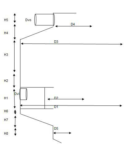
Various heights and dia of the batch vacuum pan for design aspects
( Note: These
measurements will be given a approximate values in design of vacuum pan)
Dia of Vacuum pan
D1 – Calendria shell dia ( 1.21 P
√N – P = Pitch of the tube & Number of tubes)
D2- Down take dia (0.4D1)
D3 – Vapour body dia = D1
D4 – Vapour dome dia (1.8 to 2 Dvo)
D5 – Discharge dia
Dvo – Vapour O/L dia
Dvi – Vapour I/L dia
Height of the vacuum pan
H1 – Calendria shell height ( Depends on tube
height)
H2 – Strik level height from the top tube plate ( Depends on
graining volume of pan)
H3 – Vapour space above the strik level (1200mm to 1500 mm )
H4 – (D3-D4) x Tan ∅
/2 ( ∅ = 180 to 200)
H5 – Height of the vapour dome (1.5 to 1.75 Dvo)
H6 – Bottom ring ( 150mm to 200 mm)
H7 = (D1-D5) x Tan ∝
/2 ( ∝ = 180 to 200)
H8 – 150mm to 200mm
Steam Entry
For pans with central downtake, it is
preferable to distribute the steam through several entries placed around the
calandira. The quantity of steam surging against the outer tubes immediately in
front of the steam entry produces a very rapid circulation at that point at the
beginning of the strike at the expenses of other zones of the Calandria. While
at the end of the strike, this zone near the steam entry may produce false
grain.
For this point of view it is preferable to
provide each steam entry with a conical baffle to distribute the steam and
avoid direct over heating of massecuite. For large capacities pans shall be
provided two steam entry points.
Condensate Removal
Condensate water is removed by either
inverted siphon or sealing mond. The sizing of condensate shall be calculated on
the basis of velocity of condensate having 1 m/sec.
Number of condensate points will be choosen
on the basis of calendriadia meter
Non Condenssible gases (NCG) Removal
Adequate arrangements for the removal of
condensate and incondensable gases must be made.
Generally non-condensable gasses are released
by number of perforated pipes inside calandria and connected through main line
and vented outside the pan. The total cross section are of the all NCG
connection shall be required 1 cm2 area for 10 m2 heating
surface of vacuum pan.
Sight Glasses
The batch vacuum pans are equipped with 4 – 6
sight glasses at different height from front side and one sight glass from
backside at the top level so as to facilitate easy supervision. For continuous
pan equipped with sight glasses for each compartment.
Graining Volume Calculation in Batch Pan
In this article, the concepts of the Graining
volume in batch pan and example for calculation of the graining volume are
discussed.
The Concept of Graining Volume of the Batch Pan
The graining
volume is the volume of the pan up to the level of the top
tube plate, the minimum volume at which the pan can operate.
This term “Graining Volume” is used to denote
the minimum volume of massecuite, which must be introduced in to the pan before
opening of steam valve. It is calculated corresponding to the upper surface of
top tube plate. It is also referred as ‘footing volume’ of the
pan.
Graining volume generally expressed in
percent of the working volume of the that pan. It is varies from 35 to 45%. Generally,
all types of massecuites graining made with higher purity syrup or molasses and
afterward pan is filled with low purity material. So lower graining volume is
obviously of advantage for better purity control of massecuite. Also low
graining volume is helps to increase the crystal size.
However some massecuites graining material
preparation and developing of the massecuite with same material. In such
situation, the % graining volume is not necessary to be considered for purity
reduction.
Present scenario to improve the circulation
of the pan use short length tubes . If tube length of pan decreases, then
increase in the calendria diameter for the pan with same heating surface. The
increase in calandria diameter increases the graining volume of pan.
In case of 800 mm tube
length pans, the graining volume increases upto 40 % to 42%. Such
pans definitely give higher circulation in pans.
The Graining volume of the batch pan calculated
by adding these volumes in pan
a) Bottom cone
volume
b) Bottom ring volume
c) Total tubes volumes
d) Down take Volume
e) Volume of the pan upto 50mm height from
top tube plate (It may not be required to add this volume while calculating the
graining volume)
Example of calculation of graining volume single discharge type:
|
Graining Volume of Batch Pan |
||||
|
Sl.no. |
Description |
Formula |
Values |
UOM |
|
Input
Data |
||||
|
1 |
Capacity
of pan |
60 |
T |
|
|
2 |
No. of
tubes |
N |
1306 |
nos. |
|
3 |
Tube
thickness |
t |
1.6 |
mm |
|
4 |
Tube
Length |
H1 |
750 |
mm |
|
5 |
Tube OD |
OD |
102 |
mm |
|
6 |
Dia of
pan |
D1 |
5600 |
mm |
|
7 |
Dia of
the down take |
D2 |
2400 |
mm |
|
8 |
Height of
the bottom ring |
H2 |
50 |
mm |
|
9 |
Angle of
bottom cone |
α |
18 |
Deg |
|
10 |
Discharge
Dia |
D3 |
600 |
mm |
|
Graining Volume Calculation |
||||
|
1 |
ID of the
tube |
ID = OD –
2xt |
98.8 |
|
|
2 |
Volume of
massecuite in tubes |
Q1 =
0.785 x ID x ID x H1 x N |
7.51 |
M3 |
|
3 |
Volume of
down take |
Q2 =
0.785 x D2 x D2 x H1 |
3.39 |
M3 |
|
4 |
Volume of
the bottom ring |
Q3 =
0.785 x D1 x D1 x H2 |
1.23 |
M3 |
|
5 |
Height of
the bottom cone |
h = [(D1
– D3)/2 ] x TAN α |
812.30 |
mm |
|
6 |
A1= |
0.785 x
(D1)2 |
24.62 |
M2 |
|
7 |
A2= |
0.785 x (D3)2 |
0.28 |
M2 |
|
8 |
Volume of
the bottom cone |
Q4 = h/3
(A1+A2+√A1A2) |
7.46 |
M3 |
|
9 |
Graining
Volume |
Q1+Q2+Q3+Q4 |
19.58 |
M3 |
Example of calculation of graining volume “W” type cone
|
Graining Volume of Batch Pan (“W” Type cone ) |
||||
|
Sl.no. |
Description |
Formula |
Values |
UOM |
|
Input Data |
||||
|
1 |
Capacity
of pan |
60 |
T |
|
|
2 |
No. of
tubes |
N |
1306 |
nos. |
|
3 |
Tube
thickness |
t |
1.6 |
mm |
|
4 |
Tube
Length |
H1 |
750 |
mm |
|
5 |
Tube OD |
OD |
102 |
mm |
|
6 |
Dia of
pan |
D1 |
5600 |
mm |
|
7 |
Dia of
the down take |
D2 |
2400 |
mm |
|
8 |
Dia of
bottom inverted cone |
D3 |
2200 |
mm |
|
9 |
Height of
the bottom ring |
H2 |
50 |
mm |
|
10 |
Angle of
bottom cone |
α |
18 |
Deg |
|
11 |
Angle of
bottom inverted cone |
Φ |
35 |
Deg |
|
Graining Volume Calculation |
||||
|
1 |
ID of the
tube |
ID = OD –
2t |
98.8 |
|
|
2 |
Volume of
massecuite in tubes |
Q1 =
0.785 x ID x ID x H1 x N |
7.51 |
M3 |
|
3 |
Volume of
down take |
Q2 =
0.785 x D2 x D2 x H1 |
3.39 |
M3 |
|
4 |
Volume of
the bottom ring |
Q3 =
0.785 x D1 x D1 x H2 |
1.23 |
M3 |
|
5 |
Height of
the bottom cone |
h 1 =
[(D1 – D3)/2 ] x TAN α |
552.36 |
mm |
|
6 |
A1= |
0.785 x
(D1)2 |
24.62 |
M2 |
|
7 |
A2= |
0.785 x
(D3)2 |
3.80 |
M2 |
|
8 |
Volume of
the bottom cone |
Q4 = h/3
(A1+A2+√A1A2) |
7.01 |
M3 |
|
9 |
Height of
the bottom inverted cone |
h2 = [(
D3)/2 ] x TAN Φ |
770.23 |
mm |
|
10 |
Volume of
inverted cone |
Q5 = 1/3
x 0.785 x (D3)2 h2 |
0.98 |
M3 |
|
11 |
Graining
Volume |
Q1+Q2+Q3+Q4
– Q5 |
18.17 |
M3 |
Hydrostatic Pressure in evaporator bodies |
Hydrostatic Head in Vacuum pans
This article discuss about hydrostatic
pressure definition and its calculation and also hydrostatic head in robert
type evaporator bodies and vacuum pans
Hydrostatic Head in Evaporator Bodies and Vacuum Pans
Hydrostatic pressure head definition
When a pressure ” P” is exerted on the
surface of a liquid, the pressure to which the molecules of the liquid are
subjected at a certain depth in the liquid is equal to “P ” increased by
the pressure of liquid corresponding to the depth.
Since the boiling point increases with the
pressure, if the temperature of the liquid corresponds to that necessary to
produce boiling at the surface, this boiling would increase in the liquid
layers situated at a certain depth.
Hydrostatic pressure calculation
The increase in hydrostatic pressure can be
calculated by multiplying depth of liquid column by the density of the liquid.
Hydrostatic pressure in a liquid calculated
as follows
P = ρ g H
Here P = pressure in liquid – It is measured
in meter
of water column (mwc)
or bar or atm or N/m2 or PSI or lb/ft2 or kg/cm2
ρ = density of
liquid – It is measured in kg/m3 or gm/ml or lb/ft3
g =
acceleration of gravity – Its value is 9.81 m/sec2 or 32.17405 ft/sec2
H = Depth in
the fluid where pressure is measured or height of fluid column – It is measure
in meter or feet
For Unit Conversion Factors please go through
the below link
Hydrostatic pressure in a water column where
pressure is measured or height of fluid column –
(Density of water 1gm/ml or 1000 kg/m3 )
|
Height of Water Column in meters |
Pressure in bar |
Pressure in psi |
|
1 |
0.098 |
1.42 |
|
2 |
0.196 |
2.85 |
|
3 |
0.294 |
4.27 |
|
4 |
0.392 |
5.69 |
|
5 |
0.491 |
7.11 |
|
6 |
0.589 |
8.54 |
|
7 |
0.687 |
10 |
|
8 |
0.785 |
11.4 |
|
9 |
0.883 |
12.8 |
|
10 |
0.981 |
14.2 |
|
12 |
1.18 |
17.1 |
|
14 |
1.37 |
19.9 |
|
16 |
1.57 |
22.8 |
|
18 |
1.77 |
25.6 |
|
20 |
1.96 |
28.5 |
Hydrostatic pressure in
evaporator or Hydrosatic head in Robert evaporator bodies
In a vessel of a multiple effect evaporator,
the layer of juice which is situated at the level of the bottom tube plate will
be subject to a hydrostatic pressure equal to the pressure of juice which lies
above it.
If, for example, the hydrostatic level of the
juice in the vessel corresponds to one-third of the height of the tubes, this
layer will boil at a temperature corresponding to the vapour pressure in the
vessel increased by the hydrostatic pressure to which it is subjected.
As per Peter Rein
In the evaporator bodies, the average liquid
boiling temperature should be evaluated at the average depth of liquid, which
is 0.5 x h
where h is the boiling liquid level in meters
i.e. at a pressure Ph related
to the pressure in the vapor space Pv and
the liquid density by ρL
Ph = Pv + 0.5 ρL x g x H
The optimum level is expected in Robert
evaporator bodies
of tube length of two meters is about 33% of the tube from
the bottom.
In semi-kestner type evaporator bodies, the
juice level maintained around 20% of the tube length
A significant advantage in falling film
evaporators is the absence of a hydrostatic
head effect on evaporation.
Hydrostatic head in
vacuum pan
This hydrostatic head has pronounced effect
in the boiling of massecuite as the brix of material or density goes on
increasing progressively in boiling and it plays a vital role as the boiling
point of massecuite increases with hydrostatic pressure.
The high hydrostatic head raises the boiling
point of massecuite in contact with heating surface particularly in the
massecuite of lower portions of the calendria.
So hydrostatic head plays key role on
messecuite level (strike height) on the above tube plate.
The boiling massecuite, at a temperature
of 80 to 90 0C (175 0F to 195 0F), has a specific gravity
of about 1.47 gm/ml, (density of approximately 92 lb/ft3 ) The
pressure in the massecuite will
therefore increase by about 0.15
kg/cm2 per meter (0.64 per foot) of depth.


No comments:
Post a Comment